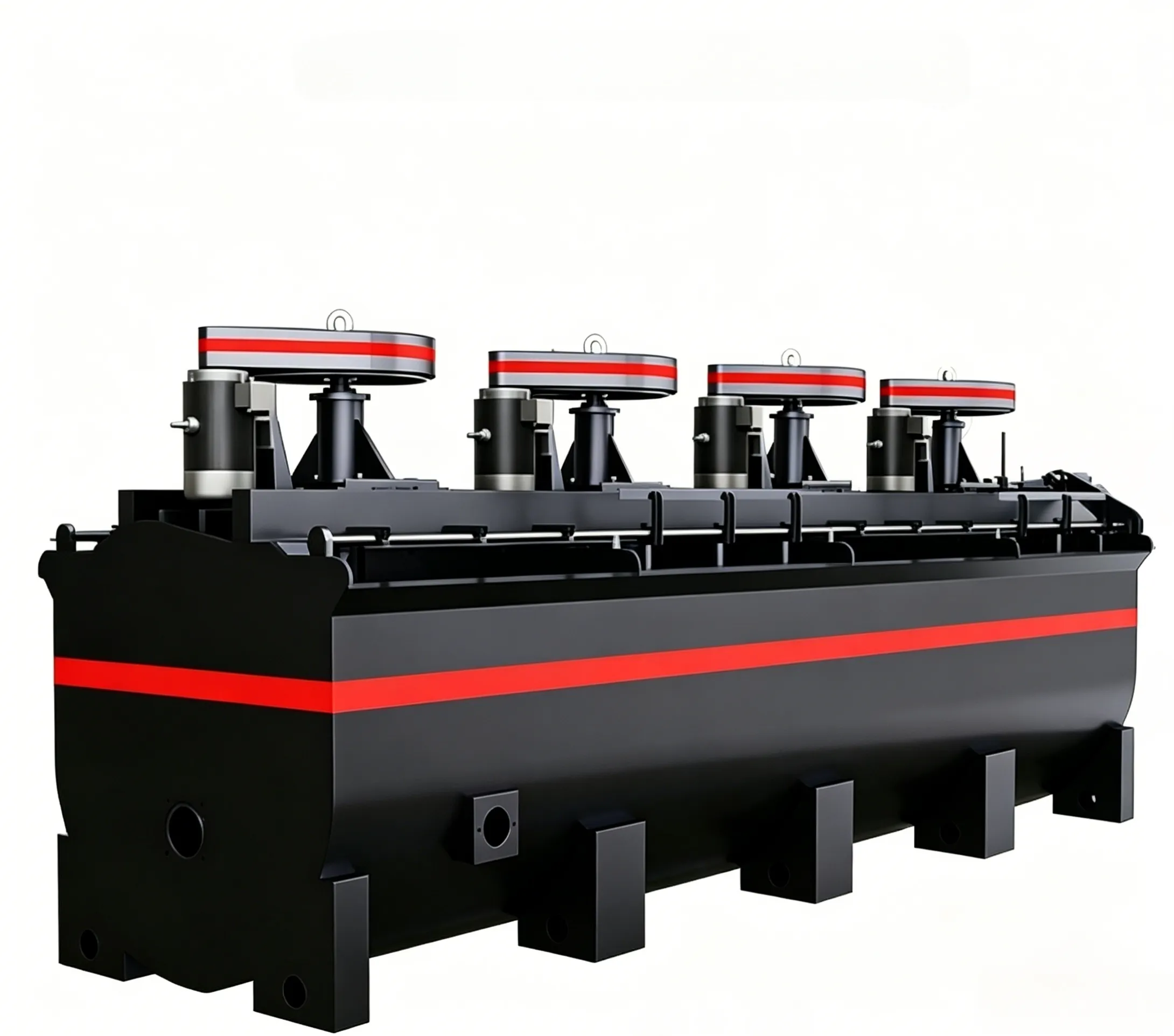
GF-Flotationsmaschine
GF-Flotationsmaschine Diese Flotationsmaschine ist für grobe Partikel ausgelegt und…


The failure of flange connecting bolts of the spiral cylinder or taper sleeve inside the hollow shaft at the feed end of a tube mill may seem simple, but it is indeed a technical problem that troubles many cement plants. The specific manifestations of bolt failure are frequent loosening and breakage of the flange connecting bolts of the spiral cylinder or taper sleeve, with bolts repeatedly tightened only to loosen again, and repeatedly replaced only to break again. This leads to separation between the hollow shaft flange of the tube mill and the flange of the spiral cylinder or taper sleeve, and even causes the spiral cylinder or taper sleeve to protrude 10–30 mm out of the hollow shaft. The material then directly scours the hollow shaft, resulting in wear of the hollow shaft as well.
Bolt fracture generally occurs at the transition between the bolt head and the shank. After fracture, the broken shank usually becomes stuck inside the threaded hole of the hollow shaft and cannot be removed, causing considerable inconvenience when replacing the bolt.
(1) Cause Analysis
The spiral cylinder of the tube mill is driven to rotate by friction with the hollow shaft flange. The contact between the spiral cylinder (or taper sleeve) and the hollow shaft generally occurs at only two locations:
① The support ring near the mill body where it fits with the inner wall of the hollow shaft. Its function is to allow free thermal expansion of the spiral cylinder while providing a support point. The fit clearance is generally 0.5–1.5 mm. However, this slight clearance causes the spiral cylinder to behave as a cantilever and also leads to wobbling of the spiral cylinder or taper sleeve.
② The connection between the outer end of the spiral cylinder (or taper sleeve) and the flange of the hollow shaft. Typically, internal threads are tapped into the end face flange of the hollow shaft, and 12 to 32 hexagonal bolts of size M16 to M30 are used to fasten the flange of the spiral cylinder (or taper sleeve) to the hollow shaft. In fact, this is the only point that secures the spiral cylinder (or taper sleeve) to the hollow shaft. Therefore, the spiral cylinder (or taper sleeve) is theoretically installed in a cantilevered manner. It is extremely important that the ring of bolts on the flange be properly tightened.
Observing the bolt failure pattern, it is found that loosening almost always precedes fracture—that is, before the connecting bolts break, they first become loose. The fracture location is often at the transition between the bolt head and the shank.
From the fracture marks, the bolts are fractured by tensile force rather than shear force. This indicates that the flange connecting bolts of the spiral cylinder (or taper sleeve) fail because of mill vibration, and more importantly, because the wobbling of the cantilever end of the spiral cylinder (or taper sleeve) is transmitted to the flange end, causing the bolts screwed into the hollow shaft flange to gradually loosen. As a result, the two flange faces lose friction and separate, causing the spiral cylinder (or taper sleeve) to slowly slide out of the hollow shaft. Under repeated impact of the flanges, the stress on the bolts gradually concentrates at the transition corner between the bolt head and the shank, leading to fatigue cracks and eventual fracture at that location.
(2) Treatment Methods
① Establish a regular inspection system. When bolt loosening is detected, tighten it immediately to reduce breakage caused by loosening. However, this approach only treats the symptoms and does not cure the root cause; it is also difficult to sustain, and the bolt loosening problem is not fundamentally solved.
② Emergency repair after bolt fracture:
a. If the broken shank is trapped inside the hollow shaft and cannot be extracted, the spiral cylinder (or taper sleeve) can be welded to the hollow shaft flange. However, this will cause difficulties when replacing the spiral cylinder (or taper sleeve) in the future.
b. Redrill holes on the flange of the spiral cylinder (or taper sleeve), retap threads on the end face flange of the hollow shaft, and tighten new bolts. This method also has some issues and is quite troublesome.
③ Improve the flange fastening method:
Add an external flange to the hollow shaft. Change the original method of using tapped holes in the hollow shaft end flange for bolted connection with the spiral cylinder (or taper sleeve) flange to a connection method using an external hollow shaft flange and the spiral cylinder (or taper sleeve) flange, with bolts, nuts, locking washers, and other fasteners to secure the two flanges. This structure provides a tightening torque on the bolts, thoroughly solving the previous problem of inadequate tightening. Even if a bolt breaks, it is easy to replace.
This modification is very advantageous for existing mill fixing arrangements and is easy to implement, thus making it a simple and practical good solution.
The welding of the new external flange to the hollow shaft must be carried out strictly according to welding quality requirements. The following points should be noted before and after welding:
a. Select reliable fasteners. Generally, studs can be used instead of bolts to avoid the manufacturing defects commonly found at the transition between the bolt head and the shank.
b. Choose appropriate welding methods, electrodes, and welding current. The site conditions during welding, such as the preparation of weld grooves, preheating before welding, and post‑weld heat preservation, must also be strictly carried out in accordance with the relevant technical requirements to prevent defects such as weld cracks, slag inclusions, and porosity.
Given the confined space at the mill head, fillet welding or lap welding is preferable for joining the new external flange to the hollow shaft.
④ Add a rigid connection between the mill end cover and the spiral cylinder. That is, install a rigid connection structure capable of accommodating a few millimeters of expansion, so that the spiral cylinder (or taper sleeve) gains an additional fixed support point beyond the end flange. This prevents the wobbling caused by the cantilevered spiral cylinder and reduces the tendency for the end flange bolts to loosen.
⑤ For large and medium‑sized mills, elastic plates can be added to the spiral cylinder (or taper sleeve) to absorb the outward thrust generated by end wobbling, thereby reducing the impact on the connecting flange and bolts, and consequently reducing bolt loosening and breakage.
 English English
 Spanish
 Russian
 Arabic
 Swahili
 French
 Turkish
 Portuguese
 Korean
 Japanese
 German
 Italian