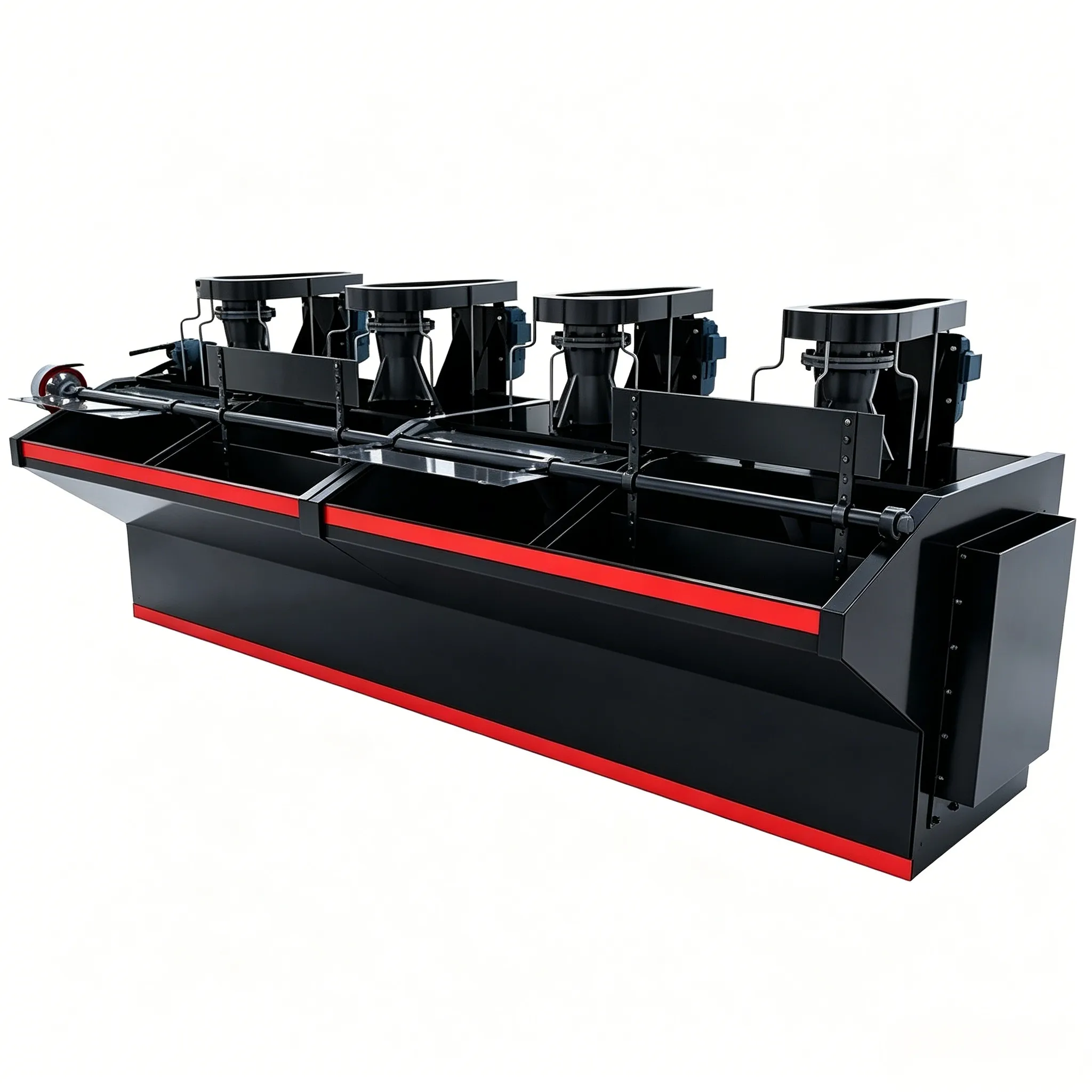
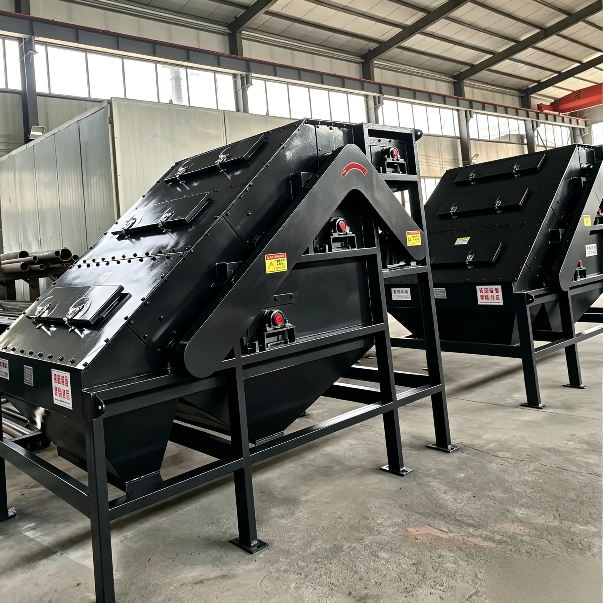
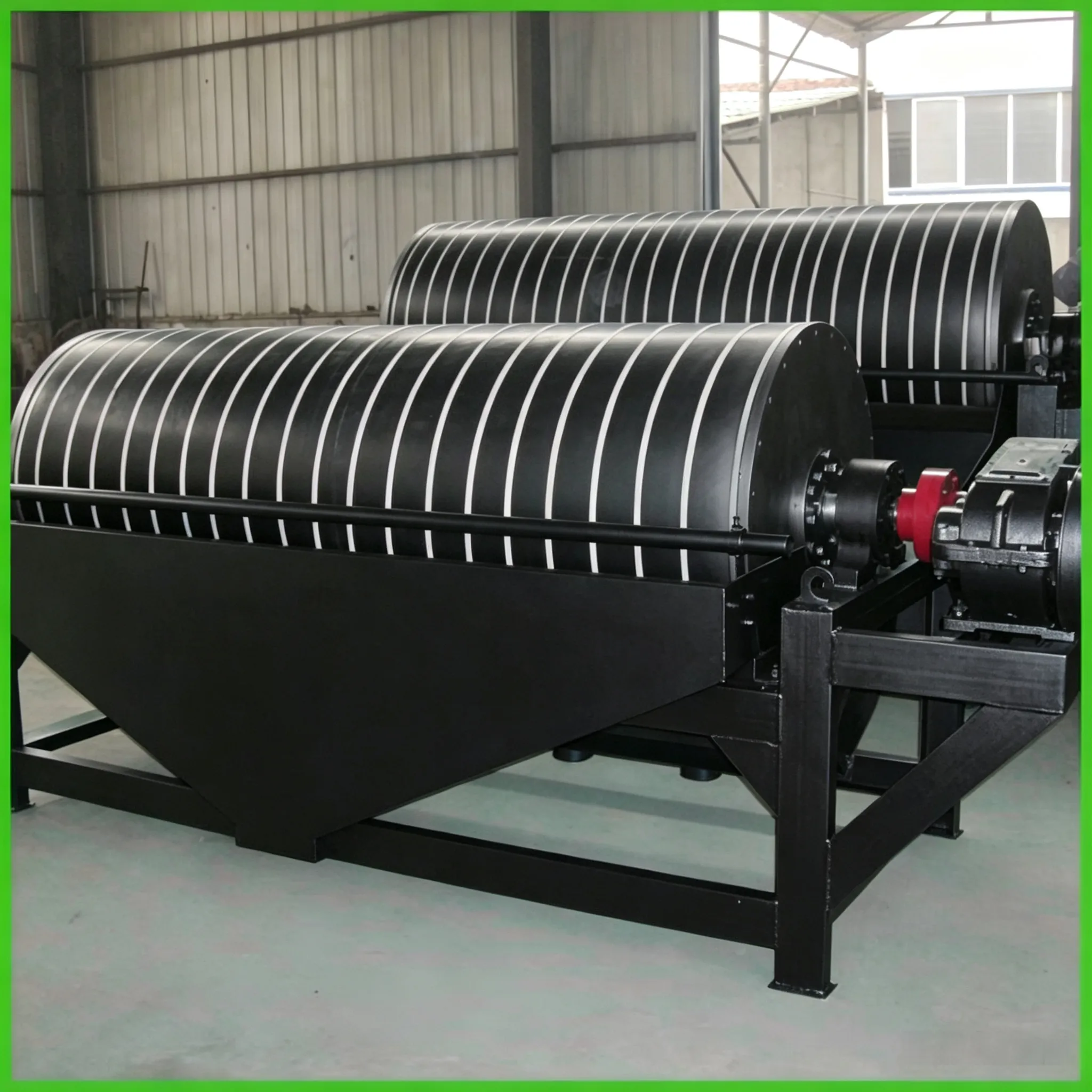
XJB-Stabflotationsmaschine
XJB-Stabflotationsmaschine Die XJB-Stabflotationsmaschine ähnelt…


Determining the operating speed of a Rohrwalzwerk essentially involves finding a balance: on one hand, the grinding media (such as steel balls) must be lifted high enough to fall with maximum impact force for crushing; on the other hand, the speed must not be so high that the media centrifuge against the shell and lose their grinding action.
This process generally consists of three steps: first calculate the “critical speed”, then determine the “theoretical optimal speed”, and finally adjust based on actual operating conditions.
This is the foundation for determining the operating speed. The critical speed is defined as the limiting speed at which the outermost layer of grinding media just rotates with the mill shell without falling. If the operating speed reaches or exceeds this value, the grinding action ceases.
The theoretical formula is:
n₀ = 42.4 / √D₀
Where:
Note: This formula is derived from idealised assumptions and serves as a theoretical reference; it is not absolutely precise.
This is the speed at which the grinding media achieve the best crushing effect. It is usually expressed as a percentage of the critical speed, and this percentage is called the “rotation rate” (ψ).
n = ψ × n₀
Regarding the optimal value of the rotation rate ψ, several mainstream views exist:
In summary, ψ = 65% ~ 85% is a widely accepted range. For practical selection, refer to the following table:
| Influencing Factor | Recommended Adjustment to ψ |
|---|---|
| Grinding method | Wet grinding (due to water lubrication) can use a speed 2–5% higher than dry grinding under the same conditions. |
| Type of grinding media | Rod mills generally operate at lower speeds than ball mills, about 60% of critical speed. |
| Grinding task | Coarse grinding may use a higher speed; fine grinding or larger shell diameters should use the lower end of the range. |
Theoretical calculations provide a starting point, but the final speed must be adjusted according to actual conditions:
In short, the procedure for determining the operating speed of a tube mill is: calculate the critical speed → choose a rotation rate of 65%–85% as a starting point based on conditions → fine‑tune during actual production.
Table 2.12 Critical speed, theoretical optimal speed, and operating speed for common tube mills
| Nominal diameter of ball mill (m) | Effective inner diameter D (m) | Critical speed n₀ (r/min) | Theoretical optimal speed n (r/min) | Operating speed n<sub>g</sub> (r/min) (calculated by the above correction formula) |
|---|---|---|---|---|
| 1.2 | 1.12 | 40.0 | 30.4 | 31.4 |
| 1.5 | 1.42 | 35.6 | 27.1 | 28.3 |
| 1.8 | 1.72 | 32.3 | 24.5 | 25.6 |
| 1.83 | 1.75 | 32.1 | 24.4 | 25.4 |
| 2.00 | 1.92 | 30.6 | 23.3 | 24.3 |
| 2.20 | 2.12 | 29.1 | 22.1 | 21.7 |
| 2.40 | 2.30 | 27.8 | 21.1 | 20.8 |
| 2.60 | 2.50 | 26.8 | 20.4 | 19.9 |
| 2.80 | 2.70 | 25.9 | 19.7 | 19.1 |
| 3.00 | 2.90 | 24.9 | 18.9 | 18.3 |
| 3.50 | 3.40 | 23.0 | 17.5 | 16.8 |
 English English
 Spanish
 Russian
 Arabic
 Swahili
 French
 Turkish
 Portuguese
 Korean
 Japanese
 German
 Italian