
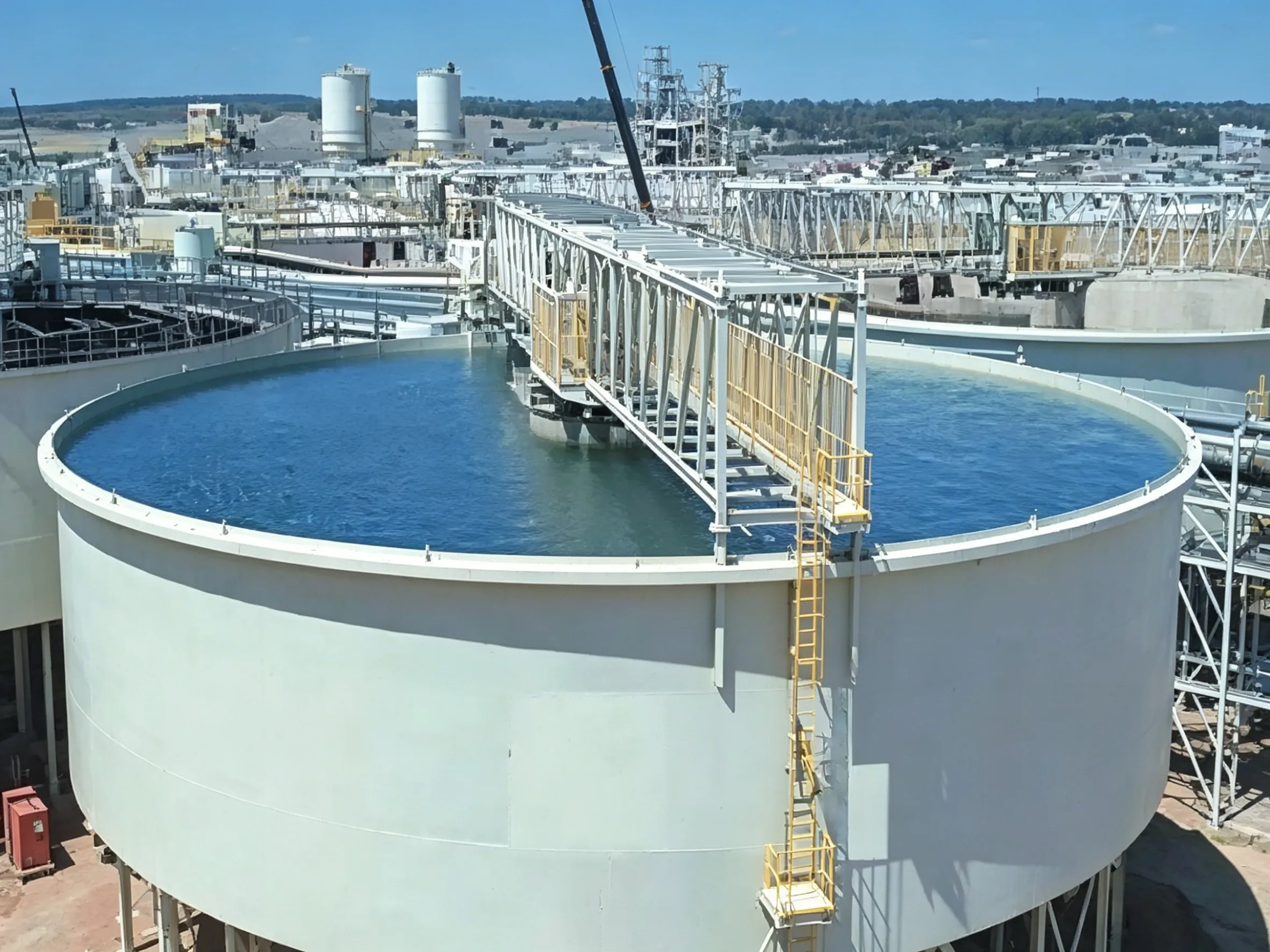
Сгуститель с периферийным приводом
Периферийный приводной сгуститель В настоящее время периферийные приводные сгустители, производимые в Китае, как правило,...
For faults and troubleshooting during thickener operation, see Table 14-10.
Table 14-10 Faults and troubleshooting during thickener operation
| Fault Condition | Cause | Elimination Method |
|---|---|---|
| Motor and reducer operate but rakes do not rotate | Safety shear pin on the drive mechanism is broken due to excessive thickener load, or the lower rake crosshead is fractured | Eliminate the cause of excessive load (e.g., high slurry concentration, debris at tank bottom), then replace the safety pin or the rake crosshead |
| Discharge hopper blocked | Coarse material, wood pieces, rags, bricks, stones, etc., have fallen into the thickener tank | First close the discharge valve, then flush with high-pressure water or empty the thickener tank for thorough cleaning |
| Unusual noise from reducer | 1. Severe bearing wear 2. Lack of oil or poor oil quality 3. Loose connecting bolts 4. Severe internal gear wear | 1. Replace bearings 2. Change oil or add lubricant 3. Tighten bolts 4. Replace severely worn gears |
| Motor overheating, vibration, unusual noise | 1. Excessive load 2. Severe motor bearing wear or lack of oil 3. Misalignment between motor shaft and reducer shaft | 1. Reduce thickener load 2. Replace bearings or add oil 3. Adjust to ensure concentricity |
According to the current maintenance work system in most Chinese concentrators, maintenance is generally classified into minor repair, medium repair, and major repair based on the scope and workload.
(1) Minor Repair
The main tasks of minor repair include:
(2) Medium Repair
The main tasks of medium repair include:
(3) Major Repair
The main tasks of major repair include:
Thickener rake frames generally come in two structural types: the simple support type integral rake frame and the cantilever beam rake frame. The former is mainly used in peripheral-drive thickeners, while the latter is mainly used in center-drive thickeners. The simple support rake frame is relatively robust, not easily deformed, and operates safely and reliably. The cantilever beam rake frame, in comparison, has lower strength and rigidity, making it more prone to deformation and loosening.
Repair of the simple support rake frame is relatively easy. Regularly check the wear degree and fixation of the rake teeth. If the rake teeth are worn down by more than half of their original height, replace or repair them to restore original dimensions. Additionally, regularly check all connection points and welds of the simple support frame; promptly tighten connection bolts and reinforce cracked welds by re-welding.
Этот cantilever beam rake frame generally has four rakes (two long, two short). One end of each rake is bolted to the rake crosshead mounted on the main shaft, while the other end is connected to the main shaft by 1–2 diagonal tension rods (hinged connections). The rakes are also connected to each other by transverse tension rods (hinged connections). All tension rods are adjustable.
Due to its structural characteristics, the cantilever beam rake frame has poor rigidity. Under excessive load, the tension rods tend to loosen, causing the rakes to twist and deform, and the bolts connecting the rakes to the crosshead may loosen. In severe cases, the crosshead may crack. Therefore, regularly check the tightness of the rake frame tension rods and adjust as required. The rake tooth connecting bolts and the bolts connecting the rakes to the crosshead should be tightened securely (use double nuts tightened and then tack-welded to prevent loosening). For small thickeners, the crosshead is generally made of gray cast iron, which is prone to cracking. It is preferable to change the material to cast steel to increase strength. The rake frame and rake teeth generally experience light wear, but if the processed slurry is highly abrasive, anti-corrosion treatment should be applied.
The drive of a center-drive thickener generally consists of an electric motor mounted on a truss, a cylindrical gear reducer, an intermediate open gear, and a large worm gear reducer that drives the main shaft and rake frame. The motor and the cylindrical gear reducer are generally connected by a pin coupling. Regularly check the wear of the pins. If the pins are severely worn and the coupling produces loud noise during operation, replace them promptly. Keep detailed records of each replacement to accurately determine the replacement cycle and schedule planned maintenance.
The cylindrical gear reducer generally experiences few problems, and its components are durable. Common issues include oil leakage at the input and output shaft seals. Solutions: (1) avoid overfilling with oil; (2) adjust or enlarge the oil baffle plate inside the bearing; (3) modify the seal type, changing from felt seals or single-lipped rubber oil seals to double-lipped rubber oil seals, and ensure no leakage at any static sealing points. If abnormal noise, impact, sudden temperature rise, or vibration occurs during operation, stop the machine immediately for inspection. Common causes: (a) bearing damage – clean and inspect all bearings, replace those with excessive clearance or obvious damage; (b) severe internal gear wear – replace gears if wear exceeds 1/4 of the tooth tip width; (c) foreign objects falling between gears and adhering to tooth surfaces, causing unstable meshing and vibration – clean and remove debris; (d) loose reducer foundation bolts causing coupling misalignment and poor open gear meshing – adjust and tighten.
For the intermediate open gear, regularly apply grease or convert to an oil-bath lubrication system. If gear tooth thickness wear exceeds 30%, replace the gear.
Этот large worm gear reducer operates at low speed and has a low failure rate. During operation, ensure proper lubrication of the worm shaft bearings to avoid bearing damage due to oil starvation. Generally, after one year of continuous operation, remove the bearings for cleaning, inspection, and scraping. For the large thrust bearing under the worm gear, prevent water or other debris from entering. Keep the bearing cavities filled with grease to avoid pitting on the balls or raceways, which would shorten bearing life. Generally, after three years of operation, clean and inspect the bearing; if pitting or pockmarks appear on the raceways or balls, replace the bearing promptly to prevent major failures.
The lower support bushing of the worm gear main shaft should be kept well-lubricated and sealed. After one year of operation, clean, inspect, and grind it. If eccentric wear is found, identify the cause and correct it promptly.
The drive of a peripheral-drive thickener generally comes in three types: roller drive, rack-and-pinion drive, and pneumatic tire drive. Regardless of the drive type, the drive mechanism is relatively simpler than that of a center-drive thickener. Typically, a motor drives a reducer, which drives a pair of open gears or a rack for two-stage speed reduction. To supply power to the motor, a collector slip ring is mounted on the central support column. Pay attention to sealing around the upper part of the slip ring to prevent rain, snow, or dust from causing poor contact, which would affect normal motor operation.
The rack should be regularly checked for deformation or looseness – once per month. Verify against the installation dimension requirements for the peripheral rack; correct any deviation promptly.
The bearings in the gear bearing housing and roller bearing housing should be greased regularly. Every 6 months, clean and inspect the bearings. If pitting or obvious damage appears, replace the bearings promptly and refill with fresh grease.
For maintenance of the central large thrust bearing, reducer, and open gears, refer to the relevant sections for the center-drive thickener described above.


