
Шаровая мельница с решетчатой разгрузкой
Конструкция шаровой мельницы с решетчатым выходом. Отличие решетчатого…
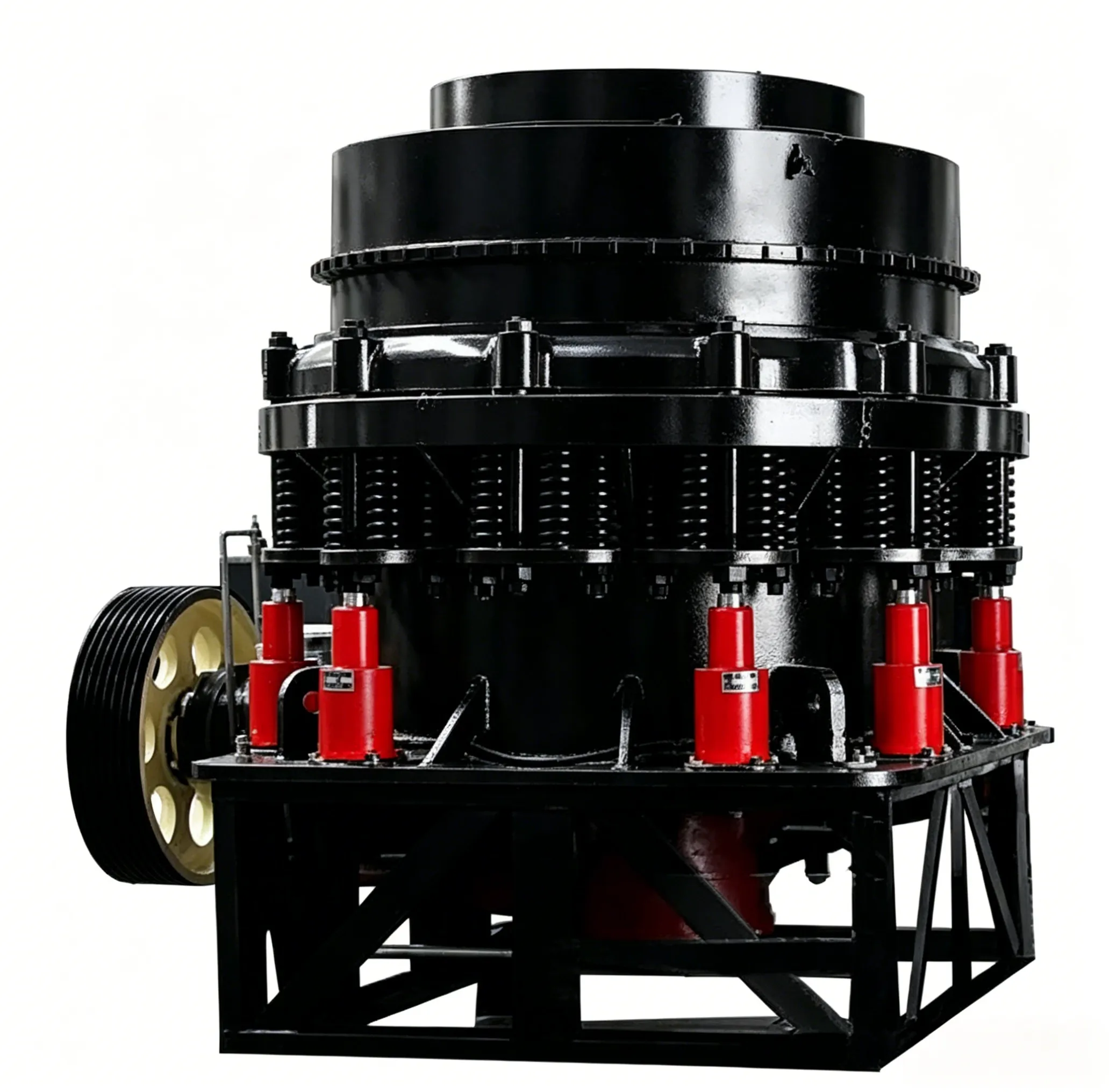
This section only describes the on-site installation of spring cone crushers. For other types of cone crushers, the similar parts may be used as reference.
4.7.1.1 Foundation
The cone crusher shall be installed on a solid reinforced concrete foundation 1, as shown in Figure 4-13. The depth and size of the foundation shall be determined according to local geological conditions. The elevation of the concrete foundation shall allow for a secondary grout layer 2 with a thickness of 50–120 mm.
To prevent accumulation of crushed ore, sufficient space shall be provided beneath the foundation for the installation of conveying equipment. The side walls at the lower part of the foundation shall be lined with protective steel plates 4 to prevent falling ore from damaging the foundation (see Figure 4-13).
Before pouring the foundation, the elevation shall be checked against the drawings and actual dimensions (measured installation dimensions of the relevant parts), and the relative positions of the anchor bolt holes shall be strictly verified. After confirming that there are no errors, the foundation may be poured.

Figure 4-13 Installation of the frame
1—Foundation; 2—Secondary grout layer; 3—Frame; 4—Protective plate; 5—Frame bushing; 6—Spirit level
Installation of the frame
The installation of the frame is shown in Figure 4-13. The frame is the main body of the crusher and serves as the foundation of the entire equipment. Therefore, it must be installed firmly and positioned accurately. The frame is installed on shim plates underneath, which facilitates adjustment and alignment. In particular, when the frame needs to be repaired or replaced after many years of service, the use of shim plates makes disassembly, installation, and adjustment much more convenient. The foundation surface on which the shim plates are placed and the surfaces of the shim plates themselves shall be scraped flat so that the shim plates bear load evenly and stably. The shim plates shall not be warped or loose. Each frame shall be supported by 8 to 12 sets of shim plates. The number of plates stacked in each set shall be minimized, ideally no more than five plates per set, with a total thickness of 50–120 mm. The shim plate sets shall be positioned close to the anchor bolts. Their installed length shall extend 10–50 mm beyond the outer edge of the frame base plate. The depth of insertion under the base plate shall exceed the centerline of the anchor bolts, and the width may be approximately 2/3 of the length. For inclined shim plates (adjusting wedges) machined from steel plates, the slope shall be 1:10 to 1:20. After installation, the shim plate sets shall be welded together to prevent movement that could affect the installation accuracy of the frame.
The levelness and verticality of the frame shall be strictly adjusted using the shim plates. The levelness adjustment shall be carried out by taking the machined annular surface of the spherical bearing housing (see Figure 4-13) as a reference and measuring with a spirit level 6. The levelness deviation shall not exceed 0.1 mm per 1000 mm. The verticality adjustment shall be checked by taking the center of the frame bushing 5 as a reference and using methods such as a plumb line. The verticality shall meet the accuracy requirements specified in the drawings. If the deviation exceeds the allowable range, correction shall be made before proceeding with installation. Otherwise, local wear of the bushing will occur, affecting the normal operation of the main shaft and the water seal dust prevention device.
After the frame has been adjusted and the bolts tightened, secondary grouting shall not be carried out immediately. Grouting shall be performed only after the entire equipment has been installed to avoid problems that would require readjustment. For the anchor bolt holes to be filled during secondary grouting, only the upper 200–400 mm section shall be grouted; the lower portion of the bolt holes shall be plugged with oil-soaked cotton yarn, dry sand, or similar material.
4.7.1.3 Installation of the drive shaft assembly
The drive shaft assembly is a component with high assembly precision requirements. Therefore, the subassembly provided by the manufacturer shall be strictly inspected. If damage, rust, inflexible rotation, or other defects are found, or if the assembly has been stored for an extended period, it shall be disassembled, cleaned, corrected, and then reassembled.
Before inserting the assembly into the frame, a gasket 3 shall be pre‑placed at the mating flange between the frame 4 and the shaft support 2 to allow adjustment of the gear meshing performance. After insertion, a template 5 shall be used to pre‑check the dimensions related to the gears. Dimensions K, L, H, M, etc. are shown in Figure 4-14. The horizontal deviation of the drive shaft shall not exceed 0.15 mm per meter of length. The axial play shall be 0.4–0.8 mm. The clearance between the shaft and its bearing shall be 2.5D/1000 to 3D/1000 (where D is the shaft diameter).

Figure 4-14 Installation of the drive shaft assembly
1—Jacking screw; 2—Shaft support; 3—Gasket; 4—Frame; 5—Template
Installation of the eccentric bushing
Before installing the eccentric bushing, first insert the adjusting washer 7 into the bottom cover 6 (see Figure 4-15). Then, assemble the thrust bearing (from bottom to top: copper, steel, copper) onto the adjusting washer 7 using the screw rod 1. During installation, pay attention to engaging the boss of the lowermost washer 5 into the groove of the bottom cover 6.
The uppermost washer 4 of the thrust bearing shall first be secured to the eccentric bushing 2 using the screw rod 5. Then, use the dedicated lifting lug on the gear 1 to insert it into the bushing (Figure 4-16).
The clearance α between the eccentric bushing 3 and the frame straight bushing 4, as well as the upper and lower clearances b and c between the main shaft 1 and its bushing 2 (Figure 4-17), are extremely important. Excessive clearances will cause improper operation, while insufficient clearances will lead to overheating or even seizure of the shaft. The clearance between the eccentric bushing and the straight bushing shall be uniform from top to bottom. As for the clearance between the main shaft and its bushing, because the main shaft axis gyrates around a fixed point, to achieve uniform contact between the main shaft and the bushing, the clearance must be smaller at the upper end and larger at the lower end. This clearance difference can be determined by graphical or calculation methods. The clearance values are empirical data and are listed in Table 4-10.

Figure 4-15 Installation of the thrust washer
1—Screw rod; 2—Frame bushing; 3—Frame; 4—Intermediate washer;
5—Washer; 6—Bottom cover; 7—Adjusting washer

Figure 4-16 Installation of the eccentric bushing
1—Gear; 2—Eccentric bushing; 3—Cylindrical pin; 4—Washer; 5—Screw rod

Figure 4-17 Clearances between the tapered bushing and the main shaft of the crushing cone, and between the eccentric bushing and the frame bushing
1—Main shaft; 2—Tapered bushing; 3—Eccentric bushing;
4—Frame bushing; 5—Frame
Table 4-10 Clearances between the tapered bushing and the main shaft of the crushing cone, and between the eccentric bushing and the frame bushing (mm)
| Equipment Specification | Clearance a between eccentric bushing and frame bushing | Clearance between tapered bushing and main shaft of crushing cone | |
|---|---|---|---|
| Upper b | Lower c | ||
| 600 | 2.0–2.5 | 2.2–2.7 | 6–7 |
| 900 | 2.2–2.7 | 2.3–2.8 | 7–8 |
| 1200 | 2.5–3.0 | 2.4–3.0 | 8–9 |
| 1750 | 3.0–3.6 | 2.9–3.6 | 9–10 |
| 2200 | 4.0–4.6 | 3.8–4.6 | 10–11 |
After the eccentric bushing, bevel gear, and other components have been smoothly installed into the frame, the gear meshing clearance shall be measured using the lead pressing method or by rotating the shaft. The clearances should be selected on the larger side, because the clearance between the eccentric bushing and the frame bushing is quite large, and the eccentric bushing always rotates against the straight bushing. Consequently, the center of the large bevel gear moves in a circular path with a radius equal to half of the clearance between the eccentric bushing and the frame bushing. If the gear meshing side clearance is too small, additional loads will be imposed on the gears and the drive shaft. The meshing of the bevel gears shall comply with the requirements specified in the design documents. In the absence of such specifications, the contact area along the tooth height and tooth length shall be not less than 40%, and the end faces of the two gears shall be flush.
Installation of the bowl bearing and the moving cone
The bowl bearing directly supports the moving cone during operation. Therefore, it must be installed firmly, and the spherical contact surfaces must be properly matched.
Before installation, the assembly shall be inspected. The spherical bearing shell 4 and the bowl bearing frame 5 must not be loose. All water passages shall not be blocked, and components such as the dust seal ring 6 and the oil baffle ring 3 shall not be damaged. The fit between the bowl bearing frame 5 and the frame 7 shall be tight (see Figure 4-18). After installation, the tightness of the horizontal contact surface shall be checked with a feeler gauge to ensure uniform contact.
After the bowl bearing has been installed, the prepared moving cone can then be installed. When inserting the moving cone into the tapered bushing, use the dedicated lifting ring on the shaft head. To avoid damaging the spherical ring, oil baffle ring, and other parts, the main shaft shall be inserted slowly, gently guiding it along point A of the tapered bushing at the counterweight block of the bevel gear.
The contact surface between the spherical surface of the head (body) 2 and the bowl-shaped bearing shell 3 shall be at the outer ring of the shell. The annular contact width shall be (0.3–0.5)R (see Figure 4-19). The number of contact points shall be not less than one point per 25 mm × 25 mm area. The wedge-shaped gap c in the non-contact area shall be 0.5–1 mm.

Figure 4-19 Contact between the bowl-shaped bearing shell and the spherical surface of the head
1—Main shaft; 2—Head (body); 3—Bowl-shaped bearing shell
Before installing the moving cone, the oil passage holes inside the main shaft 1 and the head (body) 2 shall be carefully inspected and cleaned. Installation shall proceed only after ensuring that the holes are clean and unobstructed. After installation, the fastening condition of the liners shall be checked, and the upper clamping nut shall be tightened.
Installation of the adjustment device and locking spring
This part of the installation shall be carried out only after the rotating parts have passed the test. This section mainly describes the installation of the adjustment device equipped with hydraulic thrust cylinders and locking cylinders. The mechanical adjustment and stopping device are relatively simple; reference may be made to similar sections. The installation of the adjustment device and locking spring is shown in Figure 4-20.

Figure 4-20 Installation of the adjustment device and locking spring
1—Hopper device; 2—Hopper; 3—Locking nut; 4—Pin; 5—Support sleeve;
6—Frame; 7—Spring; 8—Locking cylinder; 9—Adjustment ring
Before installation, the buttress threads on the adjustment ring 9 and the support sleeve 5 shall be carefully corrected, burrs and nicks removed, and a mixture of thick and thin oil applied to ensure smooth adjustment.
First, mount the locking cylinder 8 onto the support sleeve 5. Then mount the support sleeve onto the frame 6 and check the uniform contact of the tapered surfaces. After the adjustment ring 9 is screwed into the support sleeve 5, screw the locking nut 3 onto the adjustment ring, align it with the four pin holes on the support sleeve 5, and drive in the pins 4 for positioning.
When installing the spring device 7, adjust the compressed height of the springs according to the design requirements. If the ore is soft, the spring compression may be correspondingly reduced, but shall not be increased. The height of each set of springs shall be uniform to ensure that the crushing force is the same at each spring location.
While assembling the adjustment ring, the discharge opening shall also be adjusted. When the discharge opening is adjusted to its minimum size, the discharge opening dimensions between the crushing liner and the bowl liner shall be equal around the entire circumference. The permissible deviation shall comply with the provisions of Table 4-11.
Table 4-11 Permissible deviation of discharge opening size (mm)
| Технические характеристики | standard | short head type | ||
| output size | difference | output size | difference | |
| 600 | 12-25 | 4 | 3-15 | 2 |
| 900 | 15-50 | 5 | 3-15 | 3 |
| 1200 | 20~50 | 6 | 3~15 | 3 |
| 1750 | 25~60 | 8 | 5-15 | 4 |
| 2200 | 30-60 | 10 | 5~15 | 4 |
Installation of the water seal and lubrication device
The water seal dust prevention system is an effective measure for cone crushers to prevent dust from entering the machine body. There are two types of water supply systems: one uses open-circuit water from the concentrator’s pump station; the other is a self-circulating water supply station. The latter connects the pre-assembled water pump system (see Figure 4-21) to the inlet on the bowl bearing frame. The water pipe shall be positioned to avoid being struck or worn by the ore. On the drain pipe, a flared water connection pipe 4 shall be installed for easy observation of drainage. On the inlet pipeline, a regulating valve 2 shall be provided, as well as a shut-off valve 3 that can completely drain the water from the storage tank when the crusher stops.
The lubrication station shall be located in a place with little dust and convenient for maintenance. The installation of the lubrication station shall be completed before the crusher trial run, because at that time the lubrication system should be tested. If any fault occurs in the lubrication system, it can be disassembled and repaired beforehand.
The lubrication system shall be electrically interlocked with the main machine. That is, before starting the main machine, the oil pump must be started first; otherwise, the main machine cannot be started. This ensures that the main machine receives sufficient lubrication before operation. When the oil pump stops, the oil pressure drops below 0.05 MPa, or the oil temperature exceeds 60°C, a signal shall be sent and the main machine shall stop to prevent damage to the components.

Figure 4-21 Dust-proof water supply system
1—Water pump; 2—Regulating valve; 3—Shut-off valve; 4—Flared water connection pipe; 5—Storage tank
After the above components have been installed, a no-load test of the rotating parts shall be carried out to check the installation quality. If any improper conditions are found, they can be easily corrected before installing the adjustment ring, feed box, and other components.
Installation of the feeding part
The most important aspect of installing the feeding part is to ensure that the ore is evenly distributed around the crushing chamber via the distributing plate. This ensures a fine and uniform product size, high production capacity, smooth spring operation, and low power consumption. Otherwise, the crusher will be overloaded, the liners will experience local (one-sided) wear, resulting in a coarse and uneven product and reduced capacity. Therefore, the height and inclination angle of the feed chute, as well as the height H from the discharge opening to the distributing plate, must be correctly selected. Ensure that after the ore enters the feed box, it falls vertically onto the distributing plate, and then, by the swinging and self-rotating action of the distributing plate, the ore is uniformly distributed in the crushing chamber (Figure 4-22b). The ore must not be directed straight into the crushing chamber (see Figure 4-22a).

Figure 4-22 Installation of the feeding part
a—Incorrect position; b—Correct position
Permissible Installation Deviations for Cone Crusher
The permissible installation deviations and inspection methods for cone crushers shall comply with the provisions of Table 4-12.
Table 4-12 Permissible installation deviations for cone crushers
| Item No. | Пункт | Permissible Deviation | Unit | Метод проверки |
|---|---|---|---|---|
| 1 | Продольные и поперечные оси | 3.0 | мм | Ruler measurement |
| 2 | Elevation | ±5,0 | мм | Ruler measurement |
| 3 | Levelness | 0.1/1000 | — | Check with straightedge and spirit level |
| 4 | Coupling coaxiality | Shall comply with GB 50231 | — | Check with feeler gauge and dial indicator |


