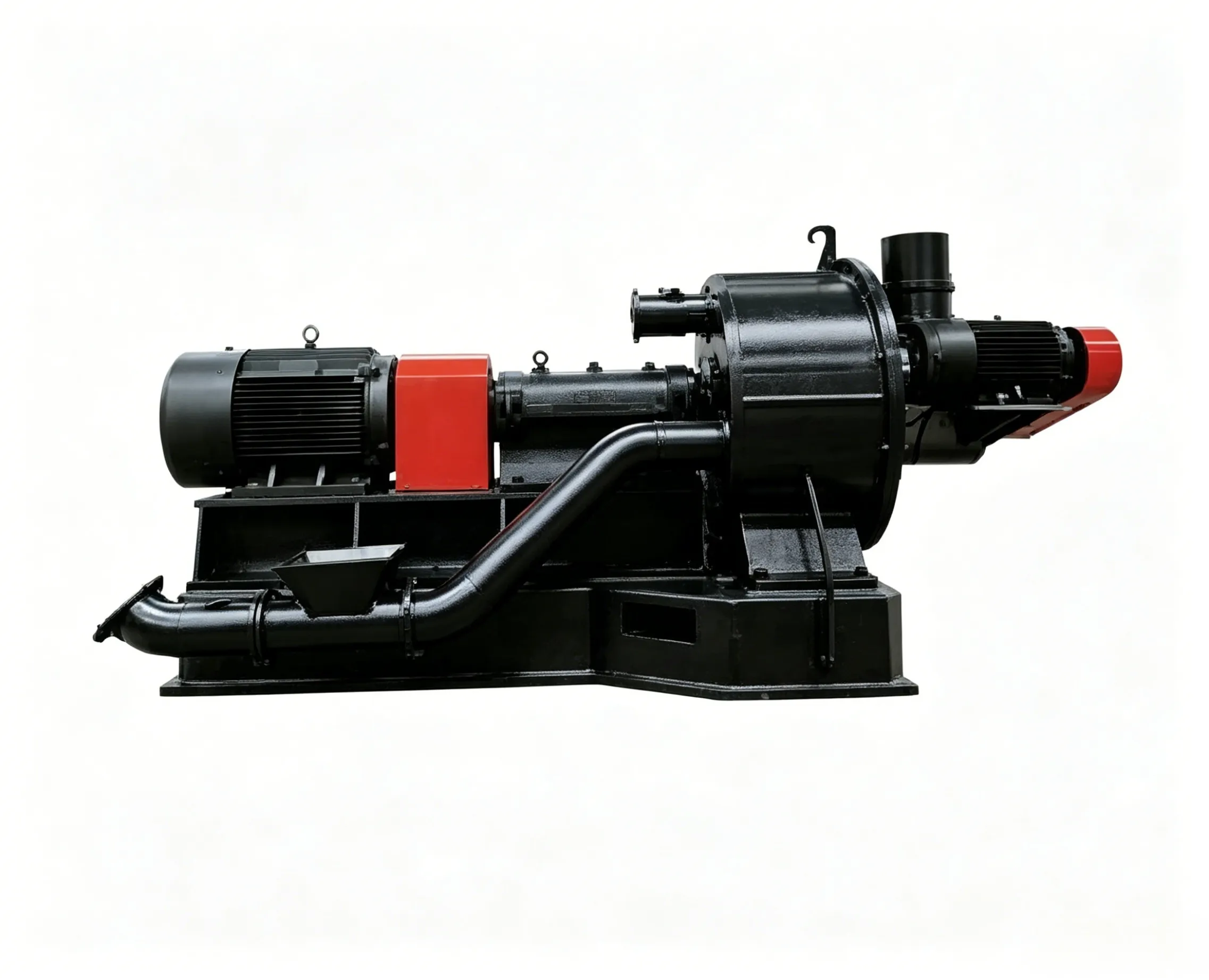
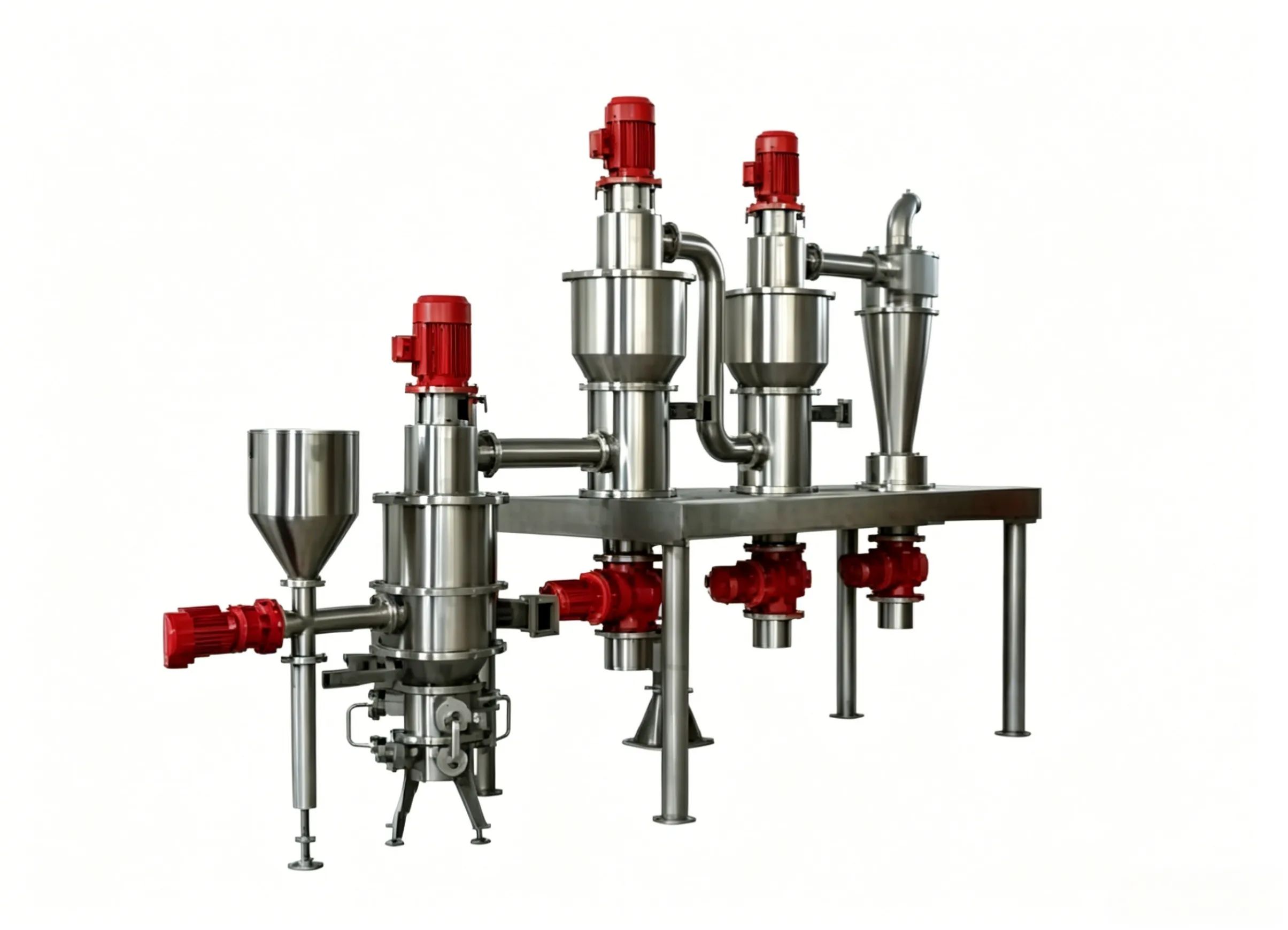
Ultra-Mikro-Prallmühle der SCR-Serie
Ultra-Mikro-Prallmühle der SCR-Serie Die Prallmühle der SCR-Serie ist eine Ultrafeinmühle…

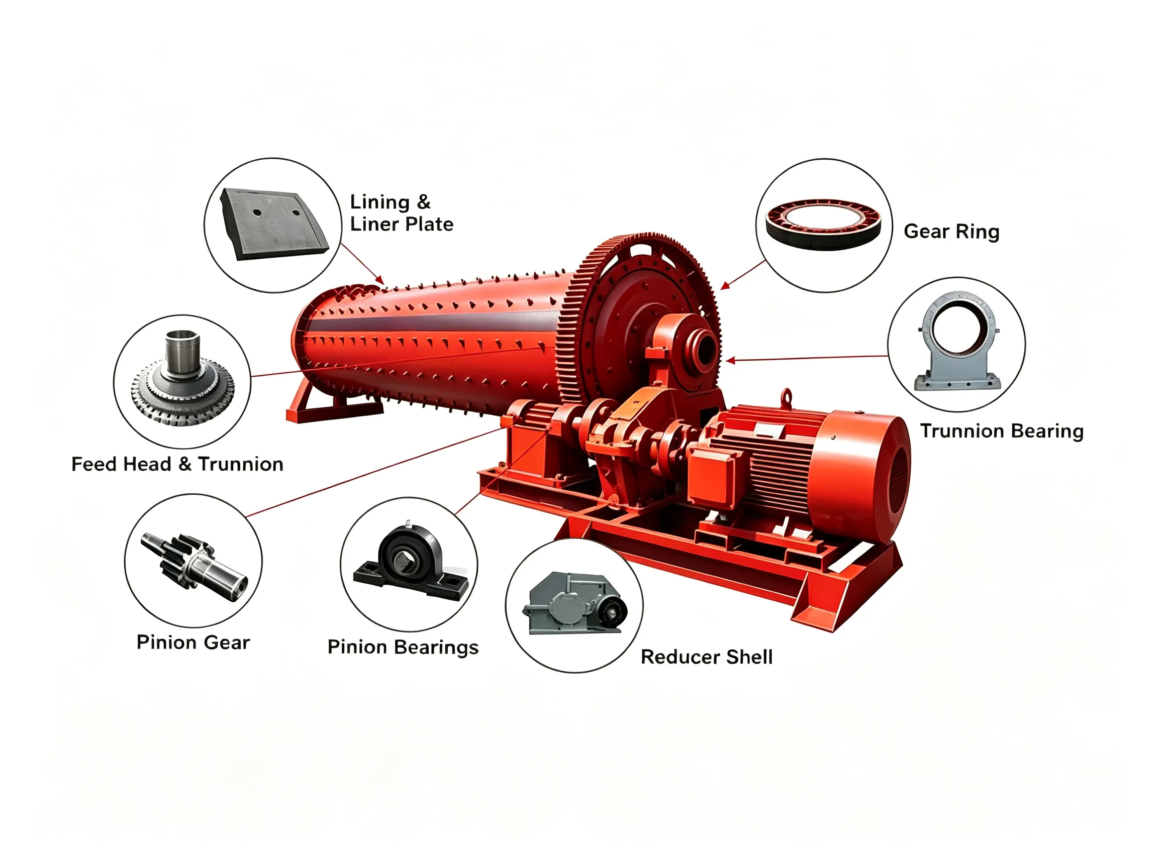
Feed End Liners for Mills
An example of feed end liners for a grinding ball mill is shown in Figure 5-80. Looking from the static mill charge toward the feed trunnion opening, the entire arrangement resembles an eye, with the contour of the innermost liner ring forming a line akin to an “eyeliner.” Although the fastest wear location on the feed end liners is related to the mill charge, the region around the charge surface height typically experiences the most rapid wear, which is generally near this “eyeliner” area. To mitigate the accelerated wear of the feed end liners (note: for SAG/AG mills, when similar materials are used, the feed end liners usually wear the fastest, followed by the grate plates; the shell liners may be comparable to the grate plates but generally wear more slowly, and the pulp lifters typically have the longest service life. In liner design, the replacement cycle must be considered, and the common practice is to make the service life of long-life components an integer multiple of the shortest cycle), lifter bars are employed to alter the original trajectory of the material, thereby reducing wear on the base plates and extending liner life.

Figure 5-80 Feed end liners for a grinding mill 1641
In terms of design, the lifter bars on the feed end liners should be reinforced. For large mills, where one‑piece liners are commonly used, the lifter bars should extend all the way to the edge of the central opening, unlike those on the grate plates. These lifters reduce the wear caused by direct friction between the mill charge and the base plates. Recently, there has been a trend toward using larger and taller lifter bars in order to prolong the service life of the base plates. For mills that operate in a single direction, the position of the lifter bars needs to be adjusted so that the lifters on the feed end liners more effectively protect the high‑wear zones. Another trend is that the lifter bars on the feed end liners are no longer rectangular but have a certain face angle, similar to the lifter bars on the shell liners, and they incorporate transition arcs at both the head and the root of the lifters. This design aims to prevent steel balls from being thrown up and impacting the shell liners near the feed end, thereby accelerating their wear.
The mechanical issues that should be considered when designing feed end liners are as follows:
(1) Ensure that each feed end liner piece fits well with the conical feed end of the mill. This can be achieved by adding rubber pads so that the liner sits properly on the mill feed end shell. A poor fit may cause bolt breakage and base plate fracture.
(2) Restrict the liner components from being directly impacted by steel balls flying in radially – for example, exposed ends, locally protruding sections, and excessively large bolt holes that are continuously subjected to the impact of the cascading ball charge, which can lead to cracking.
(3) Avoid mixing new and old liners. In such cases, the new liners will project out and remain constantly exposed to ball impact.
(4) Give preference to locating the main wear areas on the same ring of liners, so that these liners can be replaced together as a group.
(5) The feed end liners should be replaced simultaneously with the shell liners whenever possible, to prevent new feed end liners from causing accelerated wear on old shell liners.
As shown in Figure 5‑81, in order to address the fact that the feed end liners around the ring corresponding to the mill charge level experience the fastest wear, and to minimise the number of liners that need to be replaced, a special design is required for this high‑wear zone. As illustrated in Figure 5‑82, the special design includes:
(1) Manufacturing the high‑wear zone as a separate liner piece (the grey liner in the middle of Figure 5‑82).
(2) Increasing both the height and thickness of the lifter bars in this zone.

Figure 5‑81 Worn feed end liners
However, both of the above two technical solutions will increase the weight of the liners, and accordingly the setpoint of the mill charge will need to be adjusted. Therefore, in some cases, these two options may be limited, because a reduction in mill charge has a negative impact on mill throughput. An alternative solution is to change the liner material, which needs to be selected so that it can withstand the impact of large steel balls (90–140 mm) or large ore lumps (350–400 mm) while remaining economically viable. However, in SAG/AG mills the impact forces are generally very high, and conventional high‑hardness wear‑resistant materials are not suitable for such conditions. One technical approach is to insert high‑performance wear‑resistant (high‑chromium) white cast iron inserts into the lifter bars of the liners in this high‑wear zone, as shown in Figure 5‑83(a).

Figure 5‑82 Feed end liner with the wear zone isolated and raised
Usually, a liner made entirely of white cast iron is too brittle and is not suitable for this environment, but the conventional material surrounding the white cast iron protects it from impact damage. Therefore, this combination of dual-alloy materials provides both wear resistance and impact resistance, greatly extending the liner service life. Figure 5‑83(b) compares the worn condition of this liner with that of a conventional liner, showing that the wear rate of the liner made with this dual‑alloy combination in the high‑wear zone is significantly reduced.

Figure 5‑83 Wear‑resistant feed end liners
(a) High‑wear zone with white‑iron inserts;
(b) Worn conventional feed end liner and worn feed end liner with wear‑resistant inserts.
 English English
 Spanish
 Russian
 Arabic
 Swahili
 French
 Turkish
 Portuguese
 Korean
 Japanese
 German
 Italian