





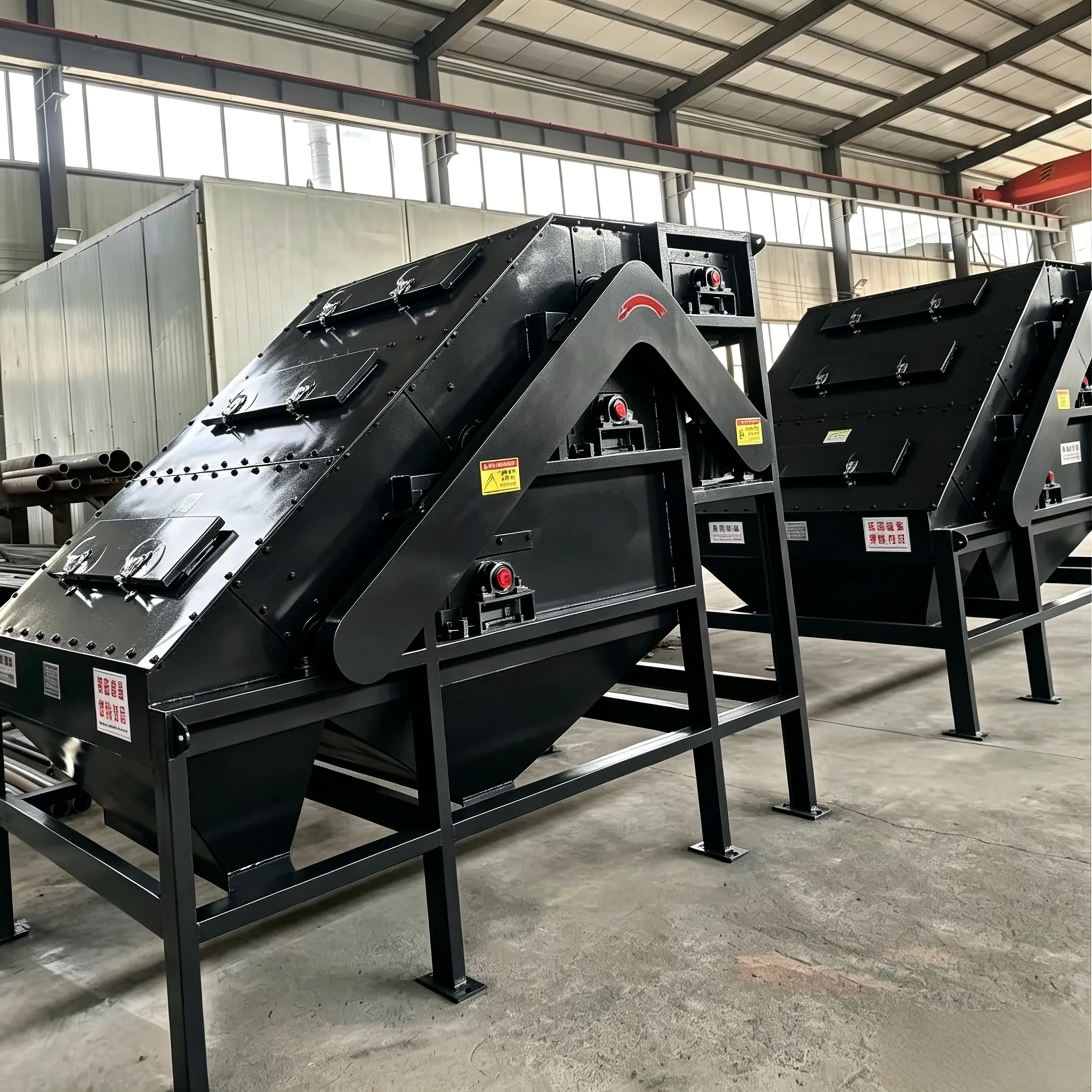
The separation principle of the high gradient magnetic separator is as follows: in a uniform magnetic field generated by an iron‑clad solenoid, a magnetic matrix such as steel wool or expanded metal mesh is placed. After being magnetized, this matrix produces a highly non‑uniform magnetic field on its radial surface, i.e., a high‑gradient magnetized field.
Construction of high gradient magnetic separator
The separation principle of the high gradient magnetic separator is as follows: in a uniform magnetic field generated by an iron‑clad solenoid, a magnetic matrix such as steel wool or expanded metal mesh is placed. After being magnetized, this matrix produces a highly non‑uniform magnetic field on its radial surface, i.e., a high‑gradient magnetized field. Thus, even with a moderately strong background field, a relatively high magnetic force can be generated. Paramagnetic materials in such a field experience a magnetic attraction force proportional to the product of the applied field and the field gradient. By utilizing this high‑gradient non‑uniform magnetic field, it is possible to separate very weakly magnetic fine particles that are difficult to separate by conventional magnetic separators, and the lower particle size limit can be reduced to as low as 1 µm, thereby improving separation performance.
High gradient magnetic separators are divided into electromagnetic and permanent‑magnet types. At present, electromagnetic types are mainly produced in China. In addition to separating weakly magnetic fine minerals, high gradient magnetic separators are also used for treating industrial wastewater: as the wastewater passes through a matrix such as steel wool, magnetic particles in the wastewater are adsorbed onto the steel wool, thus purifying the water. Therefore, they are also called high gradient magnetic filters.
Currently, the main models of high gradient magnetic separators produced in China include seven types: DMG, SLon, CHAD, CAD, CRIMM, YG1‑15, and SSS‑Z. Among these, the SLon vertical ring pulsating high gradient magnetic separator is the most widely used in China.
This is a new type of high‑efficiency continuous beneficiation equipment that utilizes a combined force field of magnetic force, pulsating fluid force, and gravity. It is suitable for separating fine weakly magnetic minerals such as hematite, manganese ore, ilmenite, and wolframite with particle sizes where ‑0.074 mm (‑200 mesh) accounts for 60%–100% (or less than 1 mm), as well as for purifying non‑metallic minerals such as kaolin, bauxite, and quartz sand.
The structure of the SLon‑1500 high gradient magnetic separator is shown in Fig. 13‑7. It mainly consists of a pulsating mechanism, an exciting coil, an iron yoke, and a rotating ring. The rotating ring is assembled from one middle ring plate and two side ring plates made of ordinary stainless steel, together with 74 trapezoidal spacer plates, forming two rows with a total of 74 separating chambers. In each separating chamber, a magnetic matrix stack is formed by alternately layering magnetic stainless steel screens (1.0 mm × 4 mm × 12 mm) and ordinary stainless steel large‑mesh screens (0.7 mm × 10 mm × 25 mm). The packing fractions of the magnetic screens and the large‑mesh screens are 12% and 3.2%, respectively.
During separation, the ring rotates clockwise. The slurry is fed from the feed hopper and passes through the ring along the gap of the upper iron yoke. Magnetic particles in the slurry are adsorbed onto the surface of the magnetic matrix and carried by the ring to the top non‑magnetic zone, where they are washed off by flushing water into the concentrate hopper. Non‑magnetic particles flow along the gap of the lower iron yoke into the tailings hopper and are discharged.
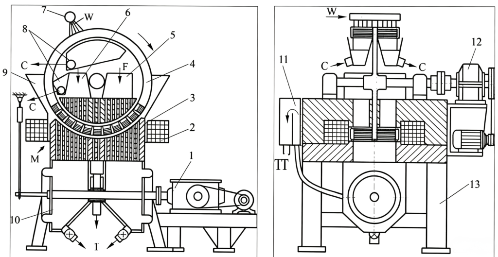
Fig. 13‑7 Structure of the SLon‑1500 high gradient magnetic separator
1—Pulsating mechanism; 2—Exciting coil; 3—Iron yoke; 4—Rotating ring; 5—Feed hopper; 6—Rinsing water; 7—Concentrate flushing water pipe; 8—Concentrate hopper; 9—Middlings hopper; 10—Tailings hopper; 11—Liquid level tank; 12—Ring drive mechanism; 13—Frame;
F—Feed; W—Clean water; C—Concentrate; M—Middlings; T—Tailings.
The features of this machine are: the ring rotates vertically, concentrate is flushed in the reverse direction, and it is equipped with a pulsating mechanism (used to eliminate mechanical entrapment). It offers the advantages of high enrichment ratio, high recovery, a wide particle size range for separation, resistance to matrix clogging, convenient operation and maintenance, and strong adaptability.
The specifications and technical parameters of this machine are listed in Table 13‑6.
Table 13‑6 Main technical parameters of SLon vertical ring pulsating high gradient magnetic separators
| Modello | Feed particle size (max.) /mm | Feed concentration /% | Slurry throughput capacity /m³·h⁻¹ | Dry ore processing capacity /t·h⁻¹ | Rated background magnetic field intensity /T | Rated exciting power /kW | Pulsating stroke /mm | Pulsating frequency /r·min⁻¹ | Machine weight /t |
|---|---|---|---|---|---|---|---|---|---|
| SLon‑500 high‑intensity | 1.0 | 10–40 | 0.5–1.0 | 0.05–0.25 | 1.0 | 13.5 | 0–50 | 0–400 | 1.5 |
| SLon‑750 high‑intensity | 1.0 | 10–40 | 0.1–2.0 | 0.1–0.5 | 1.0 | 22 | 0–50 | 0–400 | 3 |
| SLon‑1000 high‑intensity | 1.3 | 10–40 | 12.5–20 | 4–7 | 1.2 | 28.6 | 0–30 | 0–300 | 6 |
| SLon‑1250 high‑intensity | 1.3 | 10–40 | 20–50 | 10–18 | 1.0 | 35 | 0–20 | 0–300 | 14 |
| SLon‑1500 high‑intensity | 1.3 | 10–40 | 50–100 | 20–30 | 1.0 | 44 | 0–30 | 0–300 | 20 |
| SLon‑1750 high‑intensity | 1.3 | 10–40 | 75–150 | 30–50 | 1.0 | 62 | 0–30 | 0–300 | 35 |
| SLon‑2000 high‑intensity | 1.3 | 10–40 | 100–200 | 50–80 | 1.0 | 74 | 0–30 | 0–300 | 50 |
| SLon‑2500 high‑intensity | 1.3 | 10–40 | 200–400 | 100–150 | 1.0 | 94 | 0–30 | 0–300 | 105 |
| SLon‑1500 medium‑intensity | 1.3 | 10–40 | 75–150 | 30–50 | 0.4 | 16 | 0–30 | 0–300 | 15 |
| SLon‑1750 medium‑intensity | 1.3 | 10–40 | 75–150 | 30–50 | 0.6 | 38 | 0–30 | 0–300 | 35 |
| SLon‑2000 medium‑intensity | 1.3 | 10–40 | 100–200 | 50–80 | 0.6 | 42 | 0–30 | 0–300 | 40 |
| SLon‑2500 medium‑intensity | 1.3 | 10–40 | 180–450 | 80–150 | 0.4 | 63 | 0–30 | 0–300 | 60 |
13.5.2 Installation and trial operation of high gradient magnetic separator
13.5.2.1 Installation of high gradient magnetic separator
The details are as follows:
(1) The pulsating mechanism of the SLon high gradient magnetic separator generates certain horizontal and vertical vibration forces while driving the slurry to reciprocate; therefore, the machine must be installed on a solid foundation.
(2) If the installation site is close to ground level, reinforced concrete foundations are recommended.
(3) If the installation site is on an elevated floor, I‑beams welded into a planar frame are recommended as the foundation. The frame should be made as long as possible along the output stroke direction of the stroke box to increase vibration resistance. The frame should be placed on the floor, and the contact points between the frame and the floor should be as close as possible to the main load‑bearing beams and columns of the plant; the frame should be connected to the main beams or columns with bolts and nuts. For models larger than SLon‑2000, dedicated support columns from the ground floor to the upper floor are provided; models smaller than SLon‑750 have no foundation requirements.
(4) Auxiliary equipment (rectifiers, vibrating screens, and water filters) have no foundation requirements. For ease of electrical connection, the rectifier may be raised 15–20 cm above the floor or platform as appropriate.
(5) The support points of all foundation bolts of the main machine must be on the same horizontal plane. Foundation bolts should be tightened as much as possible or welded fixed, and must not be loose. When assembling the main machine, the sealing grooves between the crescent plates and the upper and lower magnetic pole heads should be coated with leak‑proof adhesive or sodium silicate adhesive.
(6) During installation, care must be taken to prevent iron filings and impurities from entering the magnetic separator.
13.5.2.2 Trial operation of high gradient magnetic separator
The trial operation steps for the high gradient magnetic separator are as follows:
(1) Before trial operation, move the feed pipe outlet of the SLon magnetic separator to the outside to prevent weld slag and iron filings from falling into the separator; then feed water and ore, confirm that coarse particles in the pipeline have been flushed out, and then move the outlet back inside.
(2) After installation, run the machine empty for several hours. The start‑up sequence is: supply water, confirm that all cooling water pipes are intact and leak‑free, start the ring, start the pulsation, start the excitation, and start the vibrating screen. After 1–2 hours, if no abnormalities are observed, stop the pulsation temporarily, then feed ore and supply rinsing water until the liquid level tank is full to the overflow surface. Then carefully restart the pulsation (since the pulsation load is highest only when the liquid level reaches the overflow surface of the tank). If the entire machine shows no significant swaying or vibration, the equipment can be operated normally.
(3) During the first few days of trial operation, check the tightness of the magnetic matrix every 2 hours. If loosening is found, stop the machine immediately to add more matrix or tighten the bolts. The newly installed matrix tends to loosen easily in the first few days; the condition will gradually improve after several adjustments.
13.5.3 Operation of high gradient magnetic separator
13.5.3.1 Preparation before start‑up
The details are as follows:
(1) Check whether the magnetic matrix is loose, and whether the pressing rod pins are broken or missing. For rod‑type matrix, check whether the clamping bolts are loose. If any problem is found, it should be corrected first.
(2) Check whether any stray iron pieces or other debris exist near the rotating parts of the separator; remove them if found.
13.5.3.2 Operating parameters
The operating parameters include: exciting current (A), pulsating stroke (mm), pulsating frequency (r/min), slurry flow rate (m³/h), and rinsing water flow rate (m³/h). The adjustment ranges for these parameters should be determined according to the corresponding beneficiation requirements.
13.5.3.3 Operating sequence
The details are as follows:
(1) Start‑up: Open water valve → Power supply → Ring → Pulsation → Excitation → Vibrating screen → Feed ore.
(2) Shut‑down: Stop feed ore → Vibrating screen → De‑energize excitation (after 2 min) → Pulsation → Ring → Power supply → Water valve.
(3) Emergency stop: Turn off power → Stop feed → Stop other units.
After de‑energizing during shutdown, the machine must run idling for at least 2 minutes to flush out accumulated strongly magnetic materials from the separator before closing water and shutting down.
13.5.3.4 Operating precautions
The details are as follows:
(1) Stopping the ring while feeding ore can easily cause matrix clogging; generally, stopping the ring during feed is not permitted. In emergency cases, first turn off the power, then stop feeding immediately. Under any circumstances, feed must be stopped when the machine shuts down.
(2) Check once per shift whether the magnetic matrix is loose, whether the pressing rod pins are broken or missing, and for rod‑type matrix, check whether the clamping bolts are loose. If any problem is found, stop the machine immediately to prevent excessive matrix wear or ring jamming.
(3) Frequently check whether the liquid level is at the same height as the overflow surface of the liquid level tank.
(4) Frequently check whether the water supply pressure is normal; the cooling water pressure for the rectifier should be controlled within the range of 0.03–1 MPa.
(5) Frequently check whether the cooling water discharge volume and temperature are normal; the outlet water temperature should not exceed 70 °C.
(6) Frequently check whether the pulsating unit and the ring are operating normally, and whether the exciting voltage and current are within the required ranges.
(7) If the cooling water pressure is too low or there is a short circuit in the exciting circuit, the rectifier protection device will automatically cut off the exciting power and the alarm bell will sound. If the alarm sounds during operation, check whether the water pressure is too low or whether there is a short circuit in the exciting circuit. After troubleshooting, press the reset button and re‑excite. If the problem cannot be resolved promptly, the machine should be shut down.
13.5.3.5 Main factors affecting beneficiation performance
The details are as follows:
(1) If the liquid level is too low, the pulsation becomes ineffective, leading to a significant decrease in concentrate grade and an increase in tailings grade. Methods to raise the liquid level include: 1) Close the tailings valve slightly; 2) Increase the feed rate; 3) Increase the rinsing water flow.
(2) Increasing the pulsating stroke or frequency, within certain limits, can improve the concentrate grade while recovery remains essentially unchanged; however, excessively high stroke or frequency will increase the tailings grade.
(3) The higher the magnetic field intensity, the lower the tailings grade, but the concentrate grade may decrease slightly.
(4) If the matrix is clogged or dirty, the beneficiation performance will be severely reduced; it should be cleaned in a timely manner.
13.5.3.6 Maintenance and lubrication schedule
The details are as follows:
(1) Clean the machine body regularly to keep the body and surrounding environment clean.
(2) The air inlet gaps must be flushed once per shift to prevent clogging.
(3) The lubrication schedule is shown in Table 13‑7.
Table 13-7 Lubrication System for SLon Magnetic Separator and Cylindrical Screen
| Equipment | Lubrication points | Lubrication diagram, item number | Number of lubrication points | Lubricating oil (fully hand-added) | The deadline for refueling and changing oil | |
| name | grade | |||||
| High gradientmagnetic separator | Swivel main shaft bearing | 1 | 2 | butter | ZG-5 | One month (keep going) |
| Large and small gears | 2 | 1 | gear oil | HL-30 | One month (keep going) | |
| Rotating ring motor | 3 | 2 | butter | ZG-5 | Two years (oil change) | |
| Rotating ring reducer | 4 | 1 | Engine oil | No. 40 | Six months (oil change) | |
| Pulsation stroke box | 5 | 1 | Engine oil | Number 40 | Three months (oil change) | |
| Pulsating motor | 6 | 2 | butter | ZG-5 | Two years (oil change) | |
Continued Table 13-7
| Equipment | Lubrication point | Lubrication diagram, item number | Number of lubrication points | Lubricating oil (fully hand-added) | The deadline for refueling and oil change | |
| name | grade | |||||
| Cylindrical screen | electric motor | 1 | 2 | butter | ZC-5 | Two years (oil change) |
| speed reducer | 2 | 1 | Engine oil | No. 40 | Six months (oil change) | |
| Large and small gears | 3 | 1 | gear oil | HL-30 | One month (keep going) | |
| Surface of the supporting roller of the cylinder | 4 | 2 | butter | ZG-5 | One week (come on) | |
| Simplified roller bearing | 4 | 4 | butter | ZG-5 | Half a year (oil change) | |
Maintenance of high gradient magnetic separator
13.5.4.1 Main machine
The details are as follows:
(1) Main shaft bearings of the rotating ring. The main shaft is equipped with a water seal to prevent slurry and water from entering the bearing housings. The shaft rotates at a very low speed, so bearing wear is minimal. As long as one cup of grease is added to each bearing housing every month, the bearing service life can reach several years. However, if lubrication is not maintained regularly and the bearings operate without oil, their service life will be greatly shortened, and replacing the bearings is also troublesome.
(2) Drive gears of the rotating ring. Both the large and small drive gears of the rotating ring are made of high‑quality steel. When installing the reducer, care should be taken to adjust the meshing clearance of the gears. If the gears are found to be insufficiently lubricated or if tooth root interference is observed, the gear clearance should be adjusted. With proper clearance and lubrication, the gear life can reach several years. Gear oil should be added once a month.
(3) Rotating ring. It is necessary to frequently check whether the magnetic matrix is loose and whether the pressing rod pins have fallen out. For rod‑type matrix, frequently check whether the clamping bolts are loose. Loose matrix can easily cause screen breakage and ring jamming, and missing rod pins or bolts can also cause ring jamming. Inspect 1–2 times per day, and correct any problems promptly to avoid ring jamming and screen breakage.
To prevent equipment damage due to ring jamming, the V‑belt from the ring motor to the reducer should not be too tight; in the event of jamming, the belt should be allowed to slip, thereby protecting other critical components.
(4) Pulsating part.
(5) Tailings valve. The tailings valve of the SLon magnetic separator must both throttle the flow and withstand the pulsating impact of the slurry, so it wears relatively quickly. Ordinary industrial valves can only last 1–3 months. For this reason, the manufacturer has developed a specially designed wear‑resistant flow control valve, whose service life is approximately ten times that of ordinary valves.
13.5.4.2 Rectifier
The primary coil of the transformer beneath the rectifier should be kept dry. Therefore, frequently check all rubber hoses and their connections for water leakage; if leakage is found, it must be corrected promptly. If the primary coil becomes damp, it should be air‑dried or dried with a fan, then the excitation current should be set to the low range for excitation. The high range may only be used after the coil is completely dry.
13.5.4.3 Vibrating screen
The details are as follows:
(1) Frequently check whether the lower support roller is rotating; the upper support roller does not necessarily need to rotate. The lower support roller supports the weight of the vibrating screen, while the upper support roller prevents the screen from damaging the gears when the screen is overloaded. In newer designs, the upper support roller has been eliminated.
(2) Regularly add lubricant to all lubrication points.
(3) Frequently check whether the screen mesh is clogged; if clogged, tap it clean with a rubber hose or replace the screen mesh.
 English English
 Spanish
 Russian
 Arabic
 Swahili
 French
 Turkish
 Portuguese
 Korean
 Japanese
 German
 Italian