1. A method for treating wastewater from a fluorite beneficiation plant, comprising the following treatment steps:
(1) graded sedimentation: sedimenting the wastewater according to the particle size of the sand and mud;
(2) electrocoagulation: placing metal electrodes in the water to be treated, passing direct current therethrough, causing the metal anode to undergo electrochemical reactions to dissolve metal ions, which then hydrolyze to produce coagulation or flocculation;
(3) air flotation for pollutant removal: by means of a large amount of hydrogen bubbles generated by electrolysis, suspended particles in the wastewater adhere to the hydrogen bubbles and float to the surface along with them, thereby being removed;
(4) horizontal‑flow sedimentation: allowing the suspended matter that has not yet settled in the air‑flotation step to undergo quiescent settling;
(5) filtering the treated liquid; and
(6) dewatering the settled solids.
2. The method for treating wastewater from a fluorite beneficiation plant according to claim 1, characterized in that the metal electrodes used in step (2) electrocoagulation are aluminum or iron.
3. The method for treating wastewater from a fluorite beneficiation plant according to claim 1 or 2, characterized in that the filtration in step (5) uses PE or PAC micro‑porous filter tubes, and said micro‑porous filter tubes are subjected to back‑washing and regeneration treatment.
4. The method for treating wastewater from a fluorite beneficiation plant according to claim 4, characterized in that the residue discharge in step (5) is carried out by rotating the sediment settled at the bottom of the tank, gathering it in the middle of the tank under the action of rake teeth following an Archimedean spiral, and discharging it by the internal pressure of the tank.
불석 선광 공장의 폐수 처리 방법
(I) Technical Field The present invention relates to a wastewater treatment method for a fluorite beneficiation plant.
(II) Technical Background Fluorite concentrate produced from fluorite beneficiation has served as a basic raw material for the fluorine chemical industry for over half a century in China. In recent years, with continuous technological progress and rising social living standards, the application fields of fluorine chemical products have become increasingly extensive, which has promoted the rapid development of the fluorite beneficiation industry, but has also brought about water pollution. In recent years, under the national policy of emphasizing energy conservation and emission reduction, the discharge standards for wastewater from the beneficiation industry have become more stringent, raising the industry access threshold for beneficiation enterprises.
At present, there are two methods for treating wastewater from fluorite beneficiation plants:
Neutralization‑precipitation with waste acid added to the wastewater: After discharge, the wastewater is directly mixed with waste acid, stirred by a wastewater pump, and then conveyed to a tailings pond for sedimentation treatment. Although this method has a simple process and low cost by treating waste with waste, it has the following disadvantages:
The pH after neutralization drops to 6.5–6, making it impossible to recycle and reuse.
The added acid easily corrodes equipment.
Waste acid is a toxic, strongly corrosive hazardous chemical, posing risks in storage and transportation.
The sediments in the tailings pond are difficult to treat.
It causes secondary water pollution.
Fluoride ions and various harmful substances cannot be removed; the effluent is turbid and fails to meet discharge standards.
It occupies a large area and involves complicated management.
The treatment speed is slow.
Coagulation‑flocculation method using inorganic electrolyte coagulants and polymeric flocculants: After discharge, the wastewater is mixed with a dilute aqueous solution of an inorganic electrolyte coagulant to produce micro‑flocculation, then polyacrylamide is added. After coagulation, the mixture is sent to the tailings pond for sedimentation treatment. Although this method involves simple equipment, neutral effluent pH, low turbidity, recyclable water, easily dewatered sludge, low reagent toxicity, some effect on reducing fluoride ions, and fast reaction speed, it has the following disadvantages:
The pH drops after treatment, increasing the cost of reuse.
The treatment cost is high.
The tailings pond entails high costs and high management expenses.
The concentrations of SO₄²⁻ and Cl⁻ increase, causing secondary pollution.
(III) Summary of the Invention The present invention aims to overcome the disadvantages of existing fluorite beneficiation plant wastewater treatment methods, such as pH drop after treatment increasing reuse costs, high treatment costs, high tailings pond costs, and secondary pollution. It provides a fluorite beneficiation plant wastewater treatment method that requires no chemical dosing, has low treatment cost, produces no secondary pollution, needs no pH adjustment, and has wide applicability.
The wastewater treatment method according to the present invention comprises the following treatment steps:
Graded sedimentation: Sediment the wastewater according to the particle size of the sand and mud.
Electrocoagulation: Place metal electrodes in the water to be treated, pass direct current, and cause the metal anode to dissolve metal ions through electrochemical reactions, which then hydrolyze to produce coagulation or flocculation.
Air flotation for pollutant removal: By means of the large amount of hydrogen bubbles generated by electrolysis, suspended particles in the wastewater adhere to the hydrogen bubbles and float to the surface for easy removal.
Horizontal‑flow sedimentation: Allow the suspended matter that has not yet settled in the air‑flotation step to settle by quiescent settling.
Filtration of the treated liquid.
Dewatering of the settled solids.
Further, the metal electrodes used in step 2 electrocoagulation are aluminum or iron.
Further, step 5 filtration uses PE or PAC micro‑porous filter tubes, and the micro‑porous filter tubes are subjected to back‑washing and regeneration treatment.
Further, the residue discharge in step 5 is carried out by rotating the sediment settled at the bottom of the tank, gathering it in the middle of the tank under the action of rake teeth following an Archimedean spiral, and discharging it by the internal pressure of the tank.
Advantages of the present invention:
The colloidal species produced are more active than those from chemical agents, and there is no concern about secondary pollution from SO₄²⁻ or Cl⁻.
It combines air flotation and oxidation, not only improving the removal of organic and inorganic substances, but also removing iron, silicon, and heavy metal ions from the water.
According to Faraday’s law, the amount of Fe(OH)₂ generated is proportional to the current. Only current control is needed to adapt to changes in water quality and flow, making operation convenient.
No pH adjustment of the water is required.
It avoids secondary pollution caused by chemical dosing; the sludge volume is small and easy to treat.
The treated water has low soluble solids content, which helps reduce the cost of reuse.
Compact structure, small footprint, saving initial investment.
Wide applicability, capable of simultaneously removing multiple pollutants, and can treat wastewater from various industries, such as printing and dyeing wastewater, electroplating wastewater, petrochemical wastewater, bathing wastewater, catering wastewater, etc.
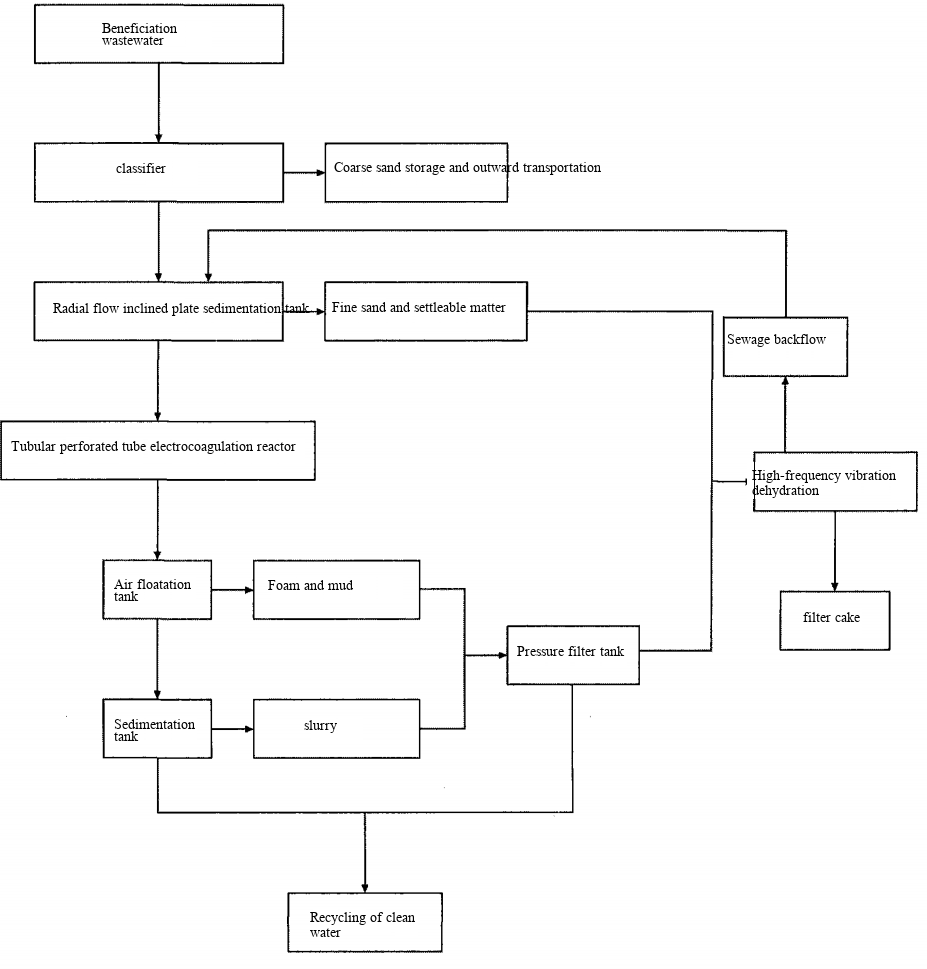
(IV) Brief Description of the Drawings Figure 1 is a process flow chart of the present invention.
(V) Detailed Description of the Embodiments
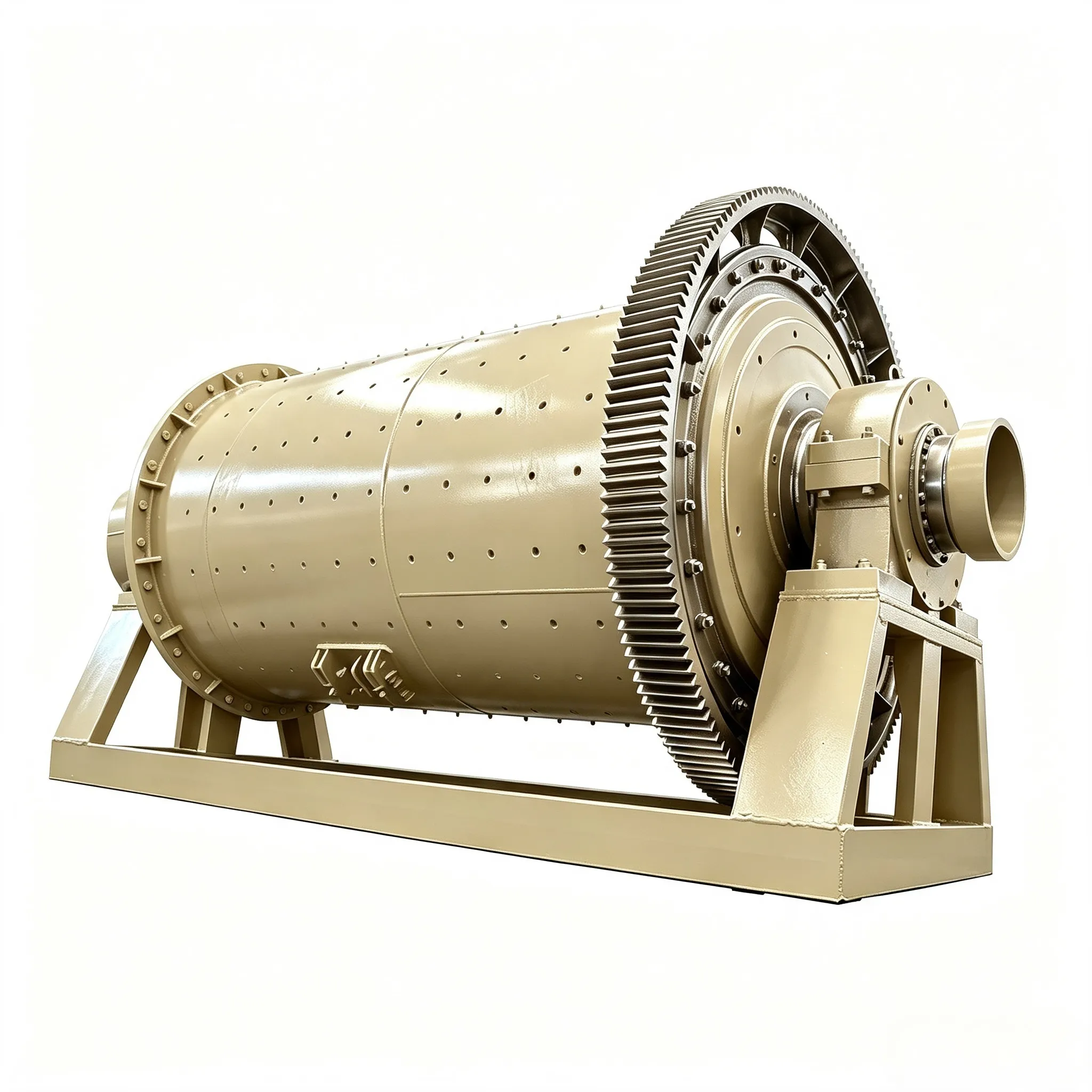
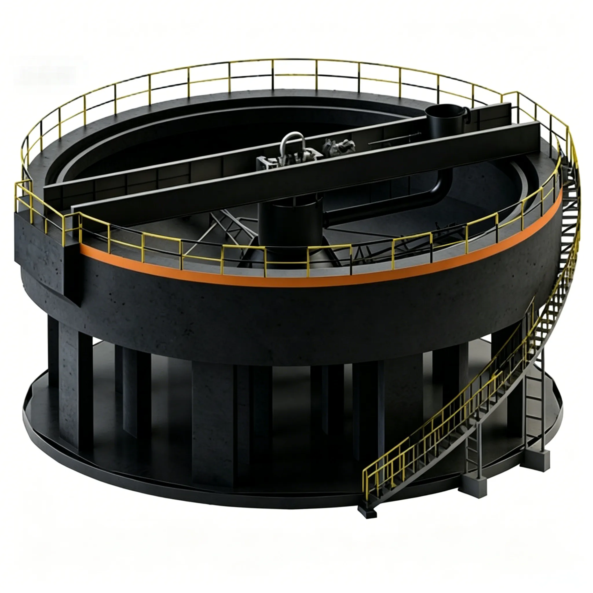
Graded sedimentation: Sediment the wastewater according to particle size of sand and mud. The equipment used is a classifier and a radial‑flow sedimentation tank. ① Working principle of the classifier: Wastewater enters the classifier from the side, passes through rectification and energy dissipation, and then enters the sedimentation zone. Coarse sand settles by gravity to the bottom and is transported upward by a rotating screw shaft (5 revolutions per minute) at an inclination of 15°, while being dewatered; the wastewater is discharged from the overflow port. ② Radial‑flow sedimentation tank: Wastewater enters from the centre of the tank. Because the diameter is much larger than the depth, the water flows radially towards the periphery. After sedimentation, the wastewater is discharged from the peripheral collecting trough. The sludge is slowly pushed by a scraper into the sludge hopper at the centre of the tank and then discharged by hydrostatic pressure.
Electrocoagulation: Metal electrodes of aluminium or iron are placed in the water to be treated. Direct current is passed, and the metal anode undergoes electrochemical reactions to dissolve Al³⁺ or Fe³⁺ ions, which hydrolyse to cause coagulation or flocculation. Taking iron as the anode, the reactions are as follows:Fe → Fe²⁺ + 2e⁻Because the fluorite beneficiation wastewater is alkaline, the reaction is:Fe²⁺ + 2OH⁻ → Fe(OH)₂At the same time, the anode reaction includes the electrolysis of H₂O to evolve O₂:2H₂O → O₂ + 4H⁺ + 4e⁻At the cathode, the main reaction is the electrolysis of H₂O to evolve H₂:2H₂O + 2e⁻ → H₂ + 2OH⁻The metal ions and their hydrolytic polymers can exert effects such as compressing the double electric layer, adsorption neutralisation, and sweep flocculation. The tiny bubbles released from the electrode surface accelerate the collision of particles. When the density is low, they float for separation; when the density is high, they sink for separation. This helps to rapidly remove dissolved and suspended colloidal compounds in the wastewater. The direct electro‑oxidation effect on the anode surface has a strong oxidising ability towards dissolved organic matter and reducing inorganic substances in the water, while the nascent hydrogen released from the anode has a relatively strong reducing effect.With the electric field inducing particle polarisation, and by means of flow channel design, the particles automatically coagulate into flocs. Without external air, the bubbles generated by electrolysis combine fully with the flocs and automatically float for removal.
Air flotation for pollutant removal: By means of the large amount of hydrogen bubbles generated by electrolysis, suspended particles in the wastewater adhere to the hydrogen bubbles and float to the surface for easy removal. This step is carried out in an air‑flotation tank.
Horizontal‑flow sedimentation: Allow the suspended matter that has not settled in the air‑flotation step to settle by quiescent settling. This is a subsequent equipment after the air‑flotation tank, mainly to provide sufficient time for the suspended matter that has not yet settled in the air‑flotation tank to settle.
Filtration of the treated liquid. PE or PAC micro‑porous filter tubes are used, and the micro‑porous filter tubes are subjected to back‑washing and regeneration treatment.The residue discharge method is as follows: The sediment settled at the bottom of the tank is rotated, gathered in the middle of the tank under the action of rake teeth following an Archimedean spiral, and discharged by the internal pressure of the tank.The equipment used is a tubular pressure filter tank: The filter tank consists of a tank body, filter tubes, back‑blow regeneration, a residue discharge mechanism, and a water discharge mechanism.
The tank body is made of high‑quality Q235 steel plate, with diameter proportional to the treatment capacity.
The filter tubes are PE or PAC micro‑porous filter tubes with relatively mature domestic technology. They can retain solid particles larger than 3 µm. When a filter cake forms on the surface of the tubes, solid particles larger than 0.4 µm cannot pass through, making the water clear. The PAC tube is a composite of activated carbon and PE material, which can also adsorb heavy metals during filtration. PE and PAC tubes are rigid porous bodies with very little deformation under tension or pressure at temperatures below 70 °C. Their capillaries are fine, curved, and labyrinthine. A filter layer forms on their surface, and it is easily stripped off by compressed air back‑washing, so they can be reused with the same effectiveness. (If the liquid is at high temperature, silicon carbide tubes can be used instead, with similar results.)
Back‑blow regeneration: When the filter layer on the tube surface becomes too thick and the filtration rate becomes too low, compressed air (0.05–0.06 MPa) is blown from the bottom of the tubes through a solenoid valve, pushing the water inside the tubes upwards and out through the water discharge valve, so that the water is discharged while the air acts on the tubes to clean them (the back‑blow time depends on the solids concentration). Since a certain number of filter tubes (the number depends on the plant’s discharge volume) are arranged in the tank, the back‑blowing is carried out in a pulsed, uninterrupted, alternate manner, so the equipment does not need to be shut down.
Residue discharge system: A material collector is located at the centre of the bottom of the tank. The sediment settled at the bottom is rotated at a speed of 1.75 revolutions per minute, and under the action of the rake teeth following an Archimedean spiral, it is gathered in the middle of the tank and discharged by the internal pressure of the tank.
Water discharge system: All filtered water is collected through pipes and discharged uniformly.
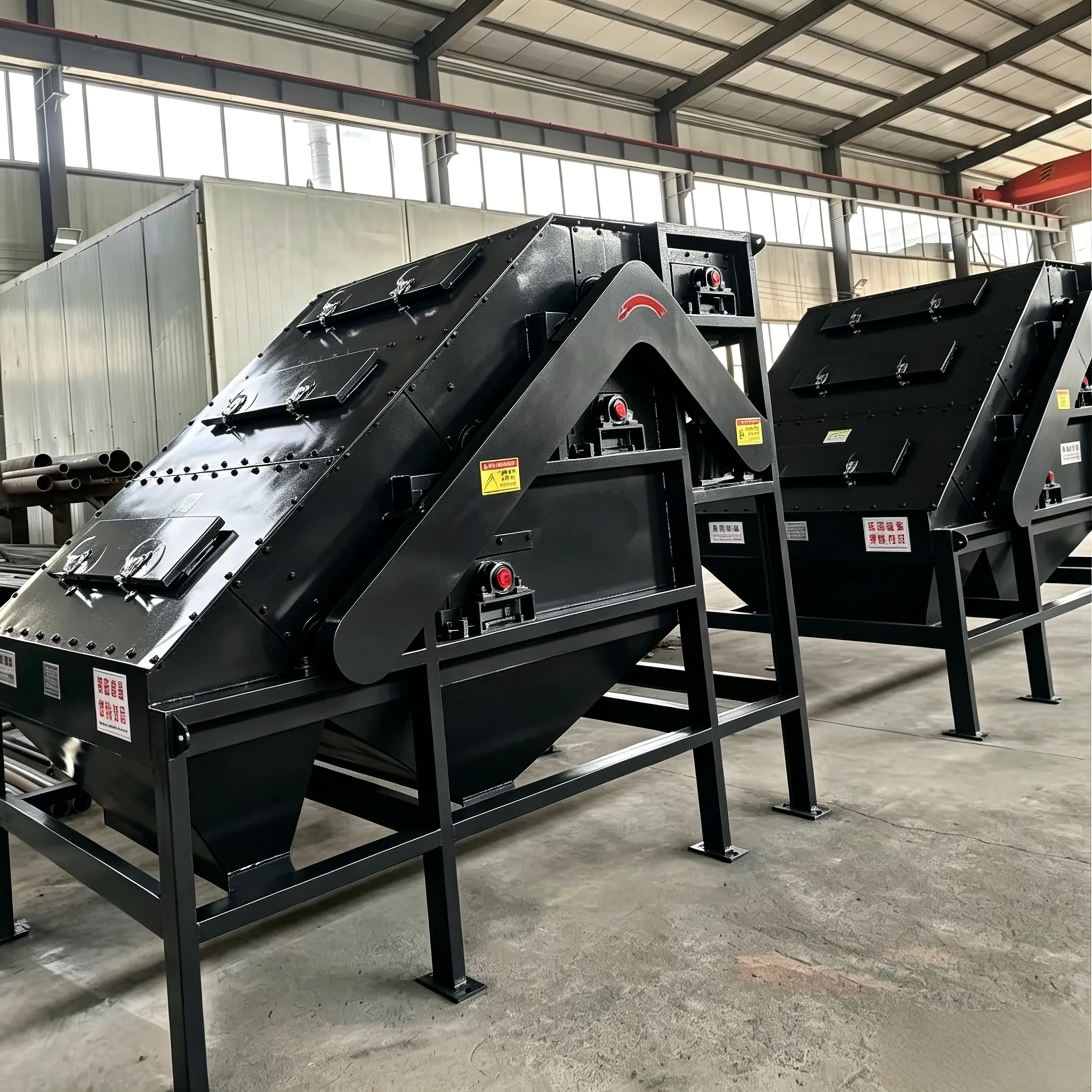
Dewatering of the settled solids. The working principle of the high‑frequency vibrating dewatering machine is that under high‑frequency vibration, the settleable solids become fluidised and are compacted, accelerating the release of interstitial water, thereby achieving dewatering.
Treatment and application of each discharged material:
The coarse sand discharged from the classifier, after stacking and further dewatering, can be used in making non‑fired bricks, building sand, and as an additive in the cement industry. It is currently in short supply on the market, with a reference price of 20 yuan/m³ (note: the original says 20元/m², likely a typo; corrected to m³ based on context).
The mud and fine sand, after dewatering by the high‑frequency vibrating dewatering machine, form a filter cake that can be used in clay bricks. After drying, it can be applied in the cement industry. The current price is 110 yuan/ton (dry basis).
The discharged clean water contains soda ash (sodium carbonate) at approximately 1 kg per ton of water. The current price of soda ash is about 2000 yuan/ton, so this corresponds to a recoverable economic benefit of about 2 yuan per ton of water.


 English
 Spanish
 Russian
 Arabic
 Swahili
 French
 Turkish
 Portuguese
 Korean
 Japanese
 German
 Italian