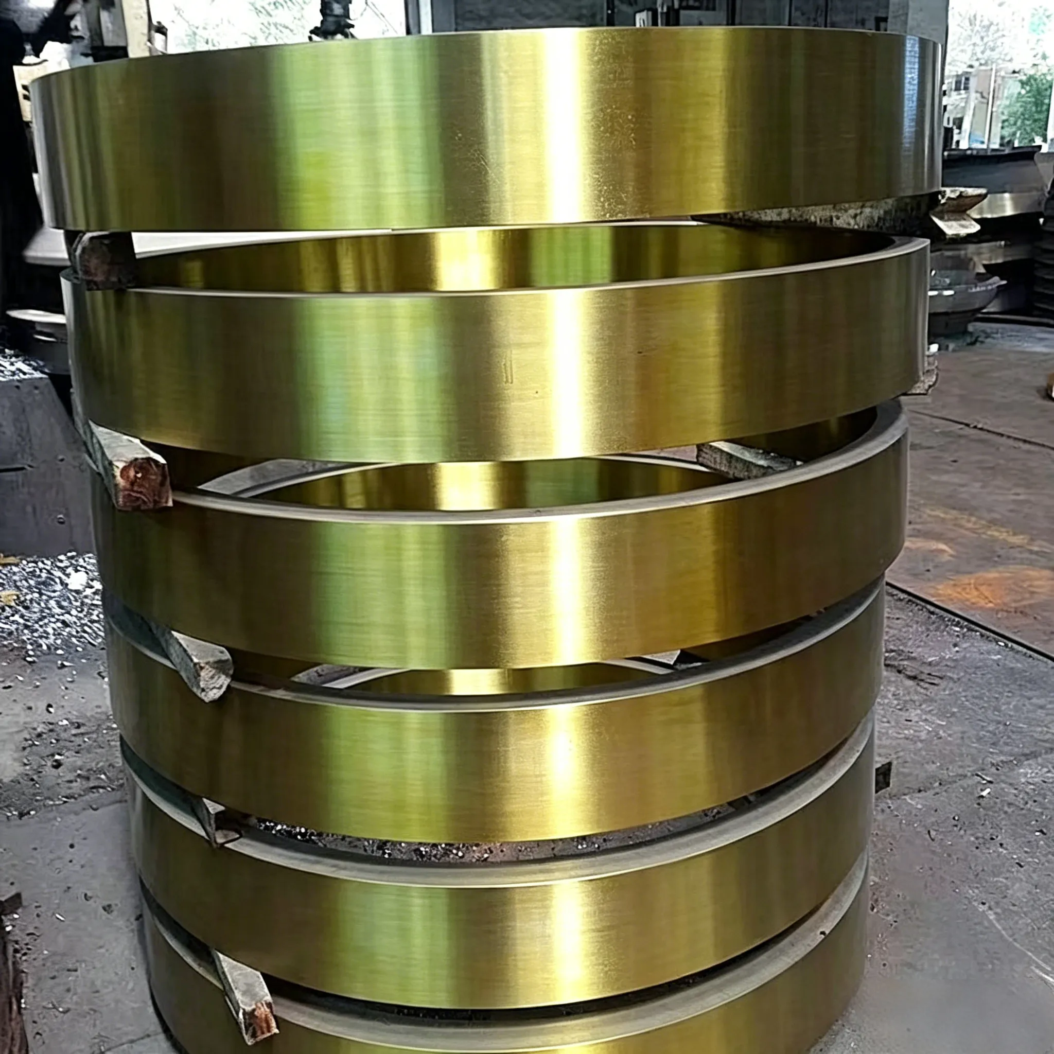
Raymond-Mühle – Mahlring
Raymond-Mühle – Mahlring – Ausführliche Produktdetailseite 1. Produktübersicht…

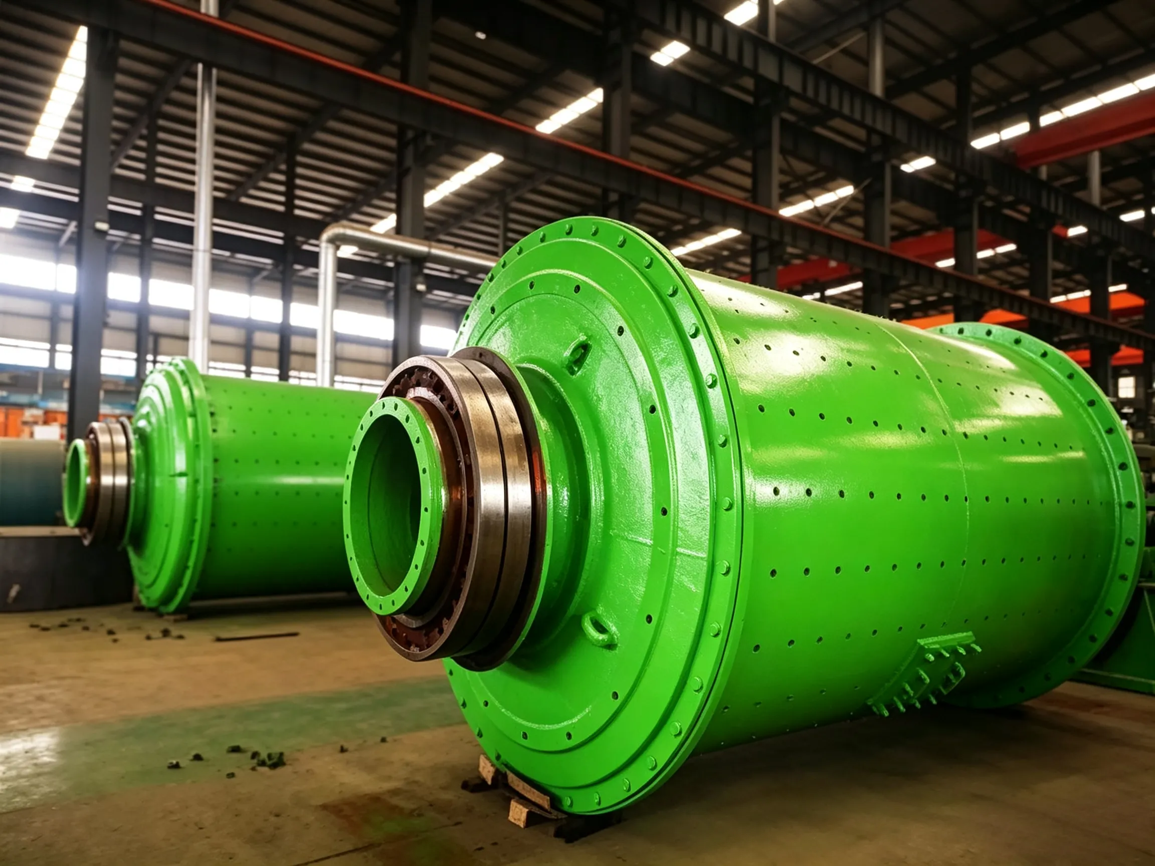
① Cracks and fractures at the feed‑end shell end cover generally occur in the fillet transition zone connecting the mill head end cover and the hollow shaft – that is, the circular arc transition between the hollow shaft and the flange plate. Casting defects such as blowholes, sand holes, cavities, and sand inclusions are commonly found at the cracked or broken locations, and the cast iron grains are usually coarse. Cracking can also occur at the weld seam between the feed‑end cover and the outer circumference of the reinforcing plate. In such cases, the weld surface and its edges are often very rough, the joint area with the end cover is uneven, undercutting is severe, and the crack depth and width both exceed 1 mm. Sometimes the end cover cracks completely through; when looking from inside the mill, light can be seen through the crack, and serious dust leakage occurs at the mill head during operation.
② Fracture of the discharge‑end shell end cover usually occurs at the junction between the end cover and the shell, appearing as a continuous circumferential crack that extends through the shell wall, causing dust leakage. Because the crack is often covered by oil stains, it is not easily detected until the hollow shaft separates from the shell – a serious consequence.
③ Shell fracture generally occurs around the manhole and liner bolt holes on the Kugelmühle shell, and then extends circumferentially.
The main reasons for cracking or fracture of the mill shell end cover and the shell include the following:
① Groove marks left inadvertently during manufacturing, transportation, and installation – these lead to cracks and fractures.
Such groove marks are often unintentionally created on the shell or end cover material – for example, by punching, stamping, or scribing with tools such as shears, centre punches, or other implements on the shell surface. Another example is when auxiliary lifting or transport fixtures welded to the shell are cut off with a flame but the remaining surface is not ground smooth and the defects are not eliminated. Welding undercut or incomplete penetration can also become crack initiation sites after the mill is placed under load. During manufacture, because the shell structure is large, most fabricators cannot perform overall heat treatment, so residual welding stresses remain in the welds and create potential crack hazards. If the weld groove is not cleaned properly or the electrodes are not dry, defects such as blowholes, sand holes, or micro‑cracks on the inner surface of the shell may form. Under alternating stress and abrasive action from the material and iron slag, these defects develop into cracks, which gradually propagate and deepen.
② Improper maintenance leads to fracture.
a. The bolts and nuts securing the end cover become “stuck” together. When replacing liners, the nuts are cut off with a flame, inadvertently damaging the end cover. Grooves created at the bolt holes gradually evolve into cracks.
b. Welding is often used as an emergency repair for cracks. If the welding technique is not adequate or the filler metal is improperly selected, the repaired area is prone to re‑cracking. For example, when patching holes with circular inset plugs, if the groove is not completely filled, a concave groove remains along the entire weld length, which can induce cracking.
③ Improper material selection leads to fracture.
a. The mill shell and end cover are subjected to repeated alternating (fatigue) stresses, so low‑carbon, relatively soft steel plates should be used. If the selected material does not meet technical requirements, has insufficient bending strength, or already contains micro‑cracks within the plate, surface cracks running in multiple directions will develop under alternating stress, eventually causing fatigue fracture.
b. For some older mills, severe local wear on the shell reduces its strength, which can also lead to cracking.
④ Mill overloading leads to fracture.
Experience shows that appropriately increasing the grinding media charge can improve mill output. However, if the charge is increased so that the shell plate stress exceeds the design specification, or if overloading occurs for other reasons, it can cause cracking or fracture of both the shell and end cover. In addition, during operation the high internal temperature and the large temperature difference between the inside and outside of the mill generate thermal stresses, which accelerate crack propagation.
⑤ Insufficient shell thickness and end cover thickness lead to fracture.
a. Although the shell thickness has a relatively large safety factor, the manhole is cut with a flame and cannot be stress‑relieved by overall annealing. The residual stress, combined with the bending stress during operation, creates a complex stress state that promotes cracking. Moreover, many bolt holes are drilled in the shell, which significantly reduces the effective safety margin of the shell thickness.
b. The end cover generally has a large flat surface but relatively thin wall thickness. During casting, uneven cooling shrinkage generates internal stresses. In addition, because the end cover intersects the hollow shaft at nearly a right angle, turbulence can occur during pouring, making quality control difficult. During operation, this fillet zone is the most sensitive area to “alternating stress” and “stress concentration”, so fracture is highly likely here. Furthermore, unreasonable weld design, improper reinforcing plate design, poor weld quality, and other structural deficiencies are also important reasons for end cover fracture.
① Prepare all necessary repair tools and equipment. Empty the grinding media from the mill and raise/support the shell so that welding is not performed while the shell and end cover are under load.
② Clean the crack (or fractured parts) and the surrounding surface of all dirt. Use a pull‑wire method or a straightedge to measure the flatness of the end cover, and at the same time check whether the crack has displaced (misalignment). Mark the measurement points and record the data for comparison with post‑weld measurements.
③ Perform a surface crack inspection, for example using the dye penetrant method. If the crack is visible from only one side, use ultrasonic flaw detection to determine the crack depth.
④ Based on the extent of damage to the cracked or fractured part, select a specific repair plan – decide whether to carry out a permanent repair (i.e., a high‑quality repair), an emergency temporary repair, or replace the part with a new one. If the fractured part is not to be replaced, continue with steps e through i below.
⑤ Drill through‑holes (stop‑holes) at both ends of the crack (including any branches), typically 5–6 mm in diameter.
⑥ Prepare a weld groove. A V‑groove is generally used. Calculate its cross‑sectional area as shown in Figure 2.32 (refer to the original figure). The groove must be machined or gouged (by air‑arc) at the crack location and at the symmetrical position on the opposite side, according to the drawing requirements.
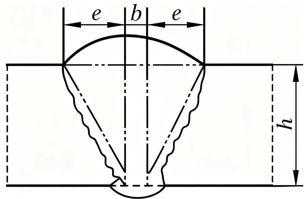
Figure 2.32 – Calculation diagram for the cross‑sectional area of a V‑groove
For a high‑quality (permanent) repair scheme, the groove cross‑sectional area A can be calculated using Formula (1):
A ≥ (b + e)h (1)
For an emergency (temporary) repair scheme, the groove cross‑sectional area A can be calculated using Formula (2):
A ≥ 2eh (2)
g. Remove all foreign matter from the groove area, such as rust, chips, oil, grease, moisture, etc.
h. Preheat the base metal; if conditions do not allow preheating, ensure that the ambient temperature reaches at least 20 °C.
i. Select the appropriate welding filler metal and calculate the required quantity. Dry the electrodes at the specified temperature. The required quantity of filler metal Q can be calculated using Formula (3):
Q = γ · A · L (3)
Where:
To prevent deformation during welding, anti‑distortion plates may be welded across the crack at intervals of approximately 500 mm along the crack length.
② Repair method for a cracked mill shell
a. Clean the steel plate at the crack location. Locate both ends of the crack and drill a stop‑hole (typically 5–6 mm diameter) at each end to prevent further propagation.
b. Use air‑arc gouging or flame cutting to cut triangular grooves (bevels) at an angle of 50°–60° on both the inner and outer surfaces of the cracked plate. To minimise shell distortion, the roots of the double‑side grooves should be kept about 2 mm apart – do not cut completely through the thickness.
c. After the groove has been shaped, use an angle grinder or grinding wheel to smooth it as much as possible, ensuring that the groove surface is even and completely free of any foreign matter, and that it exhibits a metallic sheen. After the groove has been dressed, perform a penetrant inspection to check for any other defects and to confirm that the crack ends have been eliminated. To avoid excessively reducing the shell strength, the grooving should be carried out in segments using a skip‑welding sequence. Each groove segment should be 400–500 mm long, cut at the centre of the crack, and repeated until the remaining crack length is less than 500 mm, at which point the entire crack can be welded in one pass up to the stop‑holes.
d. Welding should follow the groove preparation. If the crack is very long, use a segmented skip‑welding method. Each weld segment should be 400–500 mm long. The weld should be positioned at approximately 45° upward inclination on one side of the mill, using an uphill (progressive) welding technique. Use No. 41 electrodes (dried at 250 °C before use) or J427 electrodes (dried at 350 °C for 1 hour before use, then kept at 150 °C for holding). After removal from the oven, immediately weld two layers inside the V‑groove on the inner wall of the shell, then fill the V‑groove on the outer wall of the shell completely.
e. Chip off the two layers already welded on the inner wall, and re‑weld the groove completely. Use an angle grinder or grinding wheel to smooth the weld bead flat, then perform a penetrant inspection. If any defects are found, remove the defective portion and re‑weld. After confirming no defects remain, use an air hammer (with a round‑nose bit) to peen the weld bead twice—this both removes the slag and relieves residual stress.
f. After the groove has been filled level, perform one final penetrant inspection. If no defects are found, apply the final cover pass using high voltage, low current, and a slow travel speed. The cover layer must have a smooth surface, free from undercut defects. Any depressions at arc start/stop points should be filled and levelled by repair welding; any raised portions should be ground flush along the weld surface, with no sharp grinding marks left.
For cracks in the shell that have developed over many years of service, the repair should include wrapping the original shell with a layer of steel plate 16–20 mm thick (depending on the original shell plate thickness). The joint of this wrap plate along the mill axis direction should be single‑side welded. The wrap plate should be attached to the shell using rivets arranged in 2–3 rows along both end edges of the plate. Electric welding is prohibited for this attachment, because the lap joints are prone to cracking.
③ Repair method for cracking at the joint between the mill shell end cover and the shell (emergency repair)
a. Complete all preparatory work as described above.
b. For cracks on the inside of the shell with a gap of less than 10 mm, use oxy‑fuel cutting to form a groove, remove slag, and grind smooth.
c. For cracks on the inside of the shell with a gap greater than 10 mm, use 8 mm diameter reinforcing bars as appropriate filler material; do not cut a groove.
d. Reweld the crack between the shell and the end cover. Weld the wider sections of the crack first, then the narrower sections. Ensure that the weld bead does not protrude above the inner surface of the shell. If it does, use a portable grinder or angle grinder to smooth it flat, so that the installation of the discharge lifter bars is not hindered.
e. Weld a number of inner reinforcing ribs on the inner side of the shell, and a corresponding number of outer reinforcing ribs on the outer side, arranged in matching pairs. The number should be 10 to 20 pieces each (depending on the mill size; the reinforcement arrangement is shown in Figure 2.33). If there are existing reinforcing ribs on the outside of the shell, they should be removed before welding the new reinforcing ribs as shown in Figure 2.33; it is preferable to weld the new ribs in the original positions.
f. Inspect the quality of both the inner and outer welds, and grind them smooth.
④ Repair method for cracking of the mill shell end cover
The key point of this repair is to control distortion of the end cover after welding.
a. Complete all preparatory work as described above.
b. Remove the end cover from the mill and transport it to the repair site. Select the appropriate welding filler metal (electrodes) and calculate the required quantity. If conditions permit, preheat the end cover to a temperature of 150–200 °C.
c. Identify the crack pattern, drill stop‑holes at the ends of each branch of the crack, grind the weld groove, and make it bright and clean.
d. Determine the number of welders according to the extent of the end cover fracture. Deposit the weld metal in a planned sequence using a back‑step welding technique in sections, maintaining a flat (down‑hand) welding position throughout. From groove preparation to the completion of welding, keep the end cover working temperature at approximately 200 °C.
e. For an end cover with branching cracks, the specific welding sequence is as follows: First, weld the major crack that extends to the edge from the outside. Then turn the end cover 180° and weld the major crack that extends to the edge from the inside (full‑length welding), but fill only part of the groove height. Next, weld the branched crack portion from the inside, while simultaneously completing the remaining part of the inner major crack weld. Finally, turn the end cover 180° again and completely weld the remaining branched crack portions from the outside.
f. Immediately after the crack welding is completed, cover the entire end cover, reheat it, and hold it at temperature for more than 24 hours for stress relief, then allow it to cool naturally under the covering.
g. Before and after welding, use a pull‑wire method or a straightedge to measure the flatness of the end cover, check for any misalignment of the crack, mark the reference points, and record the data for comparison between pre‑weld and post‑weld conditions.
h. After grinding off the weld reinforcement, perform an ultrasonic inspection on the end cover; dye penetrant inspection may also be used to check for any other defects and to confirm that the cracks have been eliminated. If necessary, rework should be carried out.
⑤ Quality requirements for the repair
The surface quality of the welded joints on the tube mill shell and end cover shall meet the requirements of Grade 1 as specified in the Chinese standard JC/T 532–2007, “General technical conditions for steel welded parts in building materials machinery”.
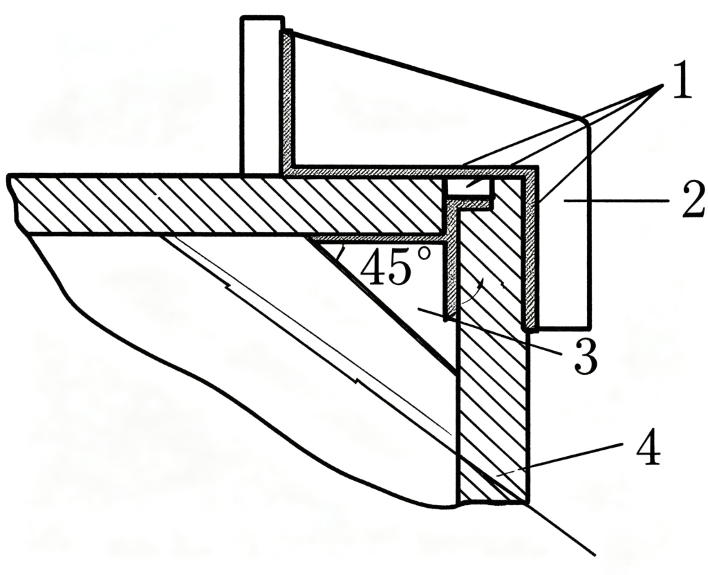
Figure 2.33 – Schematic diagram of the reinforcement method for the shell and end cover (cross‑section)
(Material: A3 and 814 steel plates)
Legend:
1 – Welded joint / Weld area
2 – Outer reinforcing rib plate (external stiffener)
3 – Inner reinforcing rib plate (internal stiffener)
4 – End cover
5 – Shell plate
 English English
 Spanish
 Russian
 Arabic
 Swahili
 French
 Turkish
 Portuguese
 Korean
 Japanese
 German
 Italian