
Since its introduction in 1924, the hammer crusher has a history of just over 80 years, but it has developed very rapidly. Owing to its advantages such as a high crushing ratio (10–40), uniform product size, little over‑crushing, low energy consumption
Since its introduction in 1924, the hammer crusher has a history of just over 80 years, but it has developed very rapidly. Owing to its advantages such as a high crushing ratio (10–40), uniform product size, little over‑crushing, low energy consumption, low equipment cost, and easy maintenance, it is widely used in industries such as cement, building materials, coal, chemicals, and metallurgical mining.
Hammer crushers can be divided into two types according to the number of rotors: single‑rotor and double‑rotor. The single‑rotor type can be further divided into reversible and non‑reversible types. The classification is detailed in Table 5‑1.

In China, hammer crushers developed slowly before the 1970s. Significant progress has been made only in the past ten years or so, resulting in the formation of general‑purpose medium‑crushing and fine‑crushing series, as well as coal‑specific medium‑crushing and fine‑crushing series, with over ten specifications. Non‑reversible hammer crushers are generally used for medium crushing, while reversible hammer crushers are generally used for fine crushing. In addition, there are single‑stage hammer crushers that can reduce materials such as limestone with a feed size of 1900 mm to below 25 mm in one stage, simplifying the traditional two‑stage or three‑stage crushing into a single stage and saving substantial capital and operating costs. In recent years, ring hammer crushers, mainly used for coal crushing, have also been developed. This is a new type of crusher with a relatively advanced structure, available in more than ten specifications. However, to date, China has not yet produced double‑rotor hammer crushers; only single‑rotor types are manufactured.
The method of indicating the model and specification of hammer crushers is not yet standardized and varies slightly among manufacturers. The general representation uses pinyin letters together with the rotor diameter D and length L, where D is the diameter of the circle traced by the tips of the hammers, and L is the effective working length of the hammers arranged along the axial direction. An example of the model specification interpretation is as follows:

General-purpose hammer crushers (PC type and PCK type) can be used in metallurgy, coal, building materials, chemical industry, electric power, and other industrial sectors. They are suitable for crushing various brittle materials such as limestone, feldspar, coal, salt, brick, gypsum, and crushed stone. The compressive strength of the material to be crushed shall not exceed 150 MPa, and the surface moisture content should be less than 2% (for the PCK type, the surface moisture can be up to below 9%). Coal-use hammer crushers (PC-M type and PCK-M type) are mainly used for crushing brittle materials such as coal and gypsum with compressive strength below 12 MPa and surface moisture below 9%. In addition, the PCB type hammer crusher is suitable for crushing various brittle materials with compressive strength below 100 MPa and moisture content not exceeding 15%. A few domestic manufacturers also produce the PCL type vertical shaft hammer crusher, which features good sealing, stable operation, low energy consumption, large production capacity, and easy maintenance. It can be used to crush limestone, coal, and other brittle materials.
Construction of a Non‑reversible Hammer Crusher
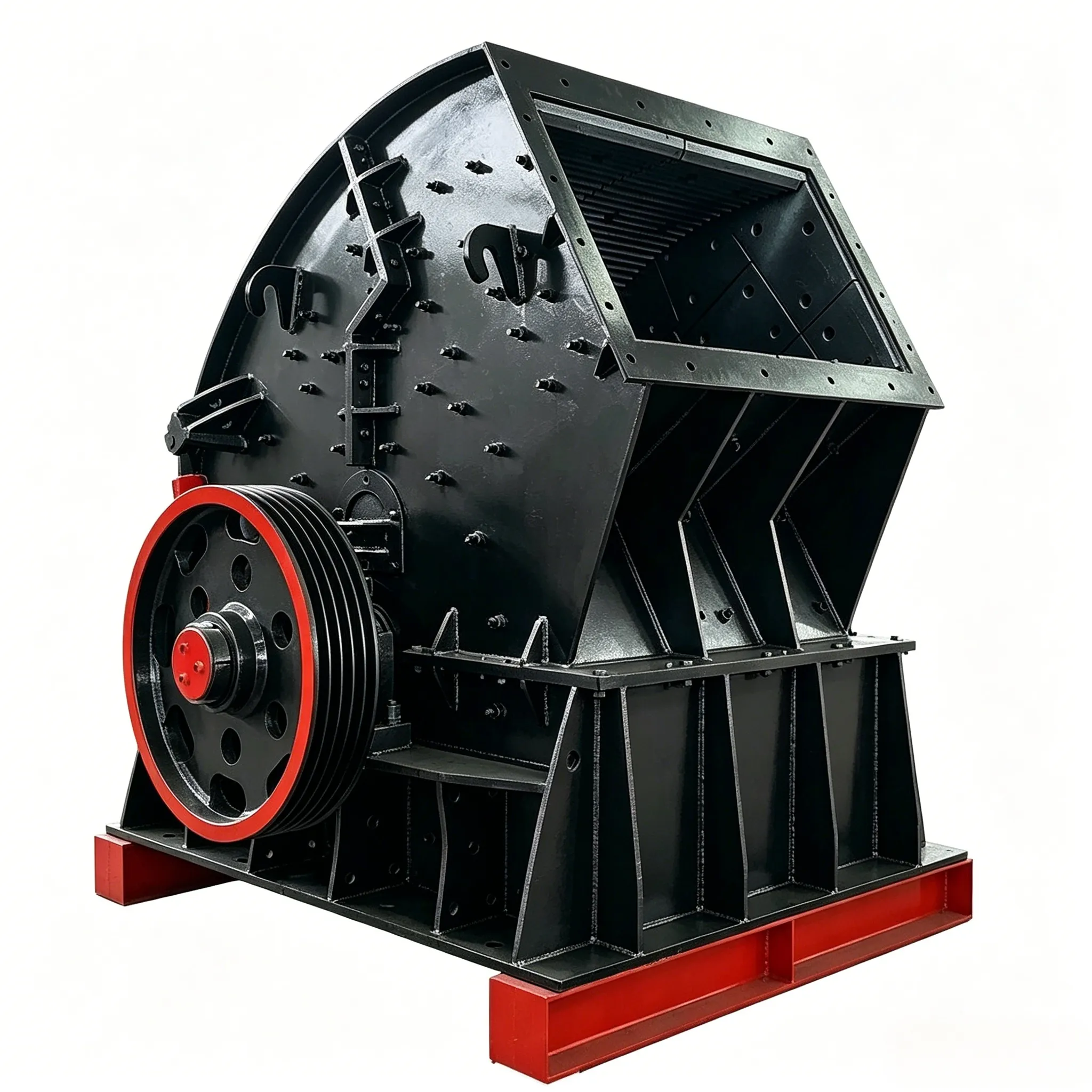
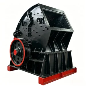
The construction of a non‑reversible hammer crusher is relatively simple. Figure 5‑1 shows the PC1600×1600 single‑rotor non‑reversible hammer crusher widely used in China. It consists of several parts: the transmission unit, rotor, main bearings, grate bars, and housing. The electric motor (1) directly drives the rotor through an elastic coupling (2). To prevent dust from entering the rolling bearings, the main bearings at both ends of the rotor shaft are placed outside the housing. They are independently supported by two rolling bearing housings (3) and are well sealed.

Figure 5‑1 φ1600 mm × 1600 mm hammer crusher
1 – Electric motor 2 – Coupling 3 – Bearing housing 4 – Main shaft 5 – Disc 6 – Pin shaft 7 – Pin sleeve 8 – Hammer head 9 – Flywheel 10 – Feed inlet 11 – Housing 12 – Impact plate 13 – Grate bar screen
The rotor consists of the main shaft (4), a number of discs (5) mounted on the shaft, and hammer heads (8). Eleven discs are arranged side by side on the main shaft. Between each pair of discs, four pin shafts (6) pass through four hammer heads (8). The entire rotor has a total of 40 hammer heads. To prevent axial movement of the hammer heads, a pin sleeve (7) (fitted over the pin shaft) is clamped between the hammer head pin hole and the disc pin hole, and the nut at the end of the pin shaft is tightened to prevent the pin sleeve from rotating. A flywheel (9) is mounted on the left end of the main shaft to reduce the non‑uniformity of rotor rotation and increase the impact energy of the hammer heads.
As can be seen from Figure 5‑1, there are two rows of pin holes on the rotor discs, with distances from the pin hole center to the axis of rotation of 440 mm and 465 mm respectively. This allows adjustment of the clearance between the hammer heads and the grate bars.
The grate bar screen (13) is installed below the rotor. It is composed of grate bars cast from high manganese steel, with the left end pressed tight by a liner plate. An impact plate (12), fitted with eight liner plates, is mounted on the right side of the rotor. After being struck by the hammer heads, the crushed material falls onto the liner plates and undergoes secondary impact crushing.
When an uncrushable object falls into the crusher, it is carried by the hammer heads to the end of the grate bar screen and discharged through a specially provided opening, thereby preventing premature wear of the inner wall of the housing and damage to certain parts.
The crusher housing (11) is a box‑type structure welded from steel plates. A feed inlet (10) is located at the top of the housing. Liner plates are installed at points on the inner wall where friction or impact from the crushed material occurs, to protect the housing from wear. For ease of inspection and repair, two small doors are provided on the front and rear walls of the housing.
The technical performance of the PC type hammer crushers produced in China is shown in Table 5‑2.
Table 5‑2 Technical performance of PC type hammer crushers
| Modelo | Tamaño de alimentación (mm) | Product size (mm) | Capacity① (t/h) | Rotor diameter② (mm) | Rotor length (mm) | Rotor speed (r/min) | Main motor | |||
|---|---|---|---|---|---|---|---|---|---|---|
| Modelo | Power (kW) | Speed (r/min) | Voltage (V) | |||||||
| PC‑M1316 | <300 | 0–10 | 150–200 | 1300 | 1600 | 740 590 735 | JS147‑8 JS147‑10 JS137‑8 | 200 200 210 | 740 590 735 | 6000 3000 380 |
| PC‑M1818 | <300 | <40 | 500 | 1800 | 1800 | 590 | JR1512‑10 | 480 | 590 | 6000 |
| PC‑M1825 | <300 | <25 | 700–750 | 1800 | 2500 | 590 | YR800‑10/1430 | 800 | 590 | 6000/3000 |
| PC‑S0604 | <100 | <35 | 12–15 | 600 | 400 | 1019 | Y180L‑4 | 22 | 1470 | 380 |
| PC‑S0806 | ≤120 | ≤15 | 20–25 | 800 | 600 | 980 | Y280M‑6 | 55 | 980 | 380 |
| PC‑S0806 | ≤120 | ≤12 | 18–24 | 800 | 600 | 1100 | JO₂‑92‑4 | 75 | 1470 | 380 |
| PC‑S0808 | ≤120 | ≤15 | 35–45 | 800 | 800 | 980 | JO₂‑92‑6 | 75 | 980 | 380 |
| PC‑S1212 | ≤200 | ≤20 | 100 | 1250 | 1250 | 735 | JS‑136‑8 | 180 | 735 | 380 |
| PC‑S1414 | ≤250 | ≤20 | 170 | 1400 | 1400 | 740 | JSQ1410‑8 | 280 | 740 | 6000 |
| PC‑S1616 | ≤350 | ≤20 | 250 | 1600 | 1600 | 595 | JSQ‑1512‑10 | 480 | 595 | 6000 |
Footnotes:
① For coal‑use hammer crushers, the capacity refers to the throughput when crushing material with a compressive strength limit of 12 MPa, surface moisture less than 9%, and bulk density of 0.8–1 t/m³. For limestone‑use hammer crushers, the capacity refers to the throughput when crushing material with a compressive strength limit of 120 MPa, surface moisture less than 2%, and bulk density of 1.6 t/m³.
② Rotor diameter refers to the path traced by the tip of the hammer head under operating conditions.
Construction of a Reversible Hammer Crusher
The non‑reversible hammer crusher has a serious disadvantage: the hammer heads wear easily on only one side. To turn the hammer heads over for reuse, the crusher must be stopped, the hammer heads removed, and then reinstalled in reverse. This consumes a lot of time, wastes labor, and reduces the operating rate. In practice, to save labor, the hammer heads are often replaced with new ones after only one side is worn, resulting in great waste.
To overcome this disadvantage, the reversible hammer crusher was developed. The rotor of this type of crusher can rotate in both forward and reverse directions. When one side of the hammer heads becomes worn, the electric motor can be reversed, and the crusher can continue to work normally for a period of time. This increases the service life of the hammer heads, improves the crusher’s operating rate, and increases production capacity.
Figure 5‑2 shows the construction of a φ1430 mm × 1300 mm reversible hammer crusher. The application range of this type of crusher is the same as that of the non‑reversible hammer crusher. However, because its rotor (10) can rotate in both directions, its main components are arranged symmetrically, and the feed inlet (18) must be placed at the top center of the machine.

Figure 5‑2 φ1430 mm × 1300 mm reversible hammer crusher
1 – Handle 2 – Cage (basket) 3 – Side plate 4 – Grate bar 5 – Eccentric wheel 6 – Pull rod 7 – Tension spring 8 – Shaft (pivot) 9 – Deflector plate (reversible plate) 10 – Rotor 11 – Electric motor 12 – Coupling 13 – Bearing housing 14 – Main shaft 15 – Disc 16 – Hammer head
17 – Pin shaft 18 – Feed inlet
As can be seen from Figure 5‑2, the main shaft (14) of the crusher is fitted with 28 discs (15). Between each pair of discs, five hammer heads (16) are suspended by pin shafts (17). The whole rotor carries a total of 70 hammer heads. The main shaft (14) is supported at both ends by rolling bearing housings (13). The electric motor (11) directly drives the rotor through an elastic coupling (12).
The discharge grate bars (4) are installed on curved side plates (3) arranged symmetrically on both sides of the rotor. The upper end of each curved side plate is suspended on a pivot shaft (8) fixed to the side walls of the housing, and the lower end rests on an eccentric wheel (5). By turning the handles (1) on both sides of the machine, the eccentric wheels (5) are rotated through a certain angle, thereby adjusting the clearance between the hammer heads and the grate bars to ensure the required product size. This adjustment can be made without stopping the crusher. To ensure that the side plates remain in constant contact with the eccentric wheels during operation, a tension spring (7) is attached to the lower end of each side plate. The spring tension prevents the side plates from bouncing on the eccentric wheels due to material impact on the grate bars.
To prevent uncrushed material or tramp objects from being carried by the hammer heads to the other side of the rotor and causing accidents, the lower ends of the left and right side plates are spaced apart, with no grate bars in this region. An adjustable swing‑type cage (2) (also called a “hard‑coal basket”) is installed at the lower end. Any uncrushed material falls into this basket. By periodically pulling the pull rod (6) that extends outside the housing, the operator can discharge the accumulated uncrushed material from the basket.
| Modelo | inlet size/mm | output size/mm | capacity/t ·h-¹ | Rotor diameter②/mm | rotro length/mm | rotor speed /r·min-¹ | motor | |||
| modelo | power/kW | rotatioon speed rmin- | V | |||||||
| PCK-1413 | ≤80 | ≤3 | 400 | 1430 | 1300 | 985 | JS1410-6 | 520 | 985 | 3000 |
| JS158-6 | 550 | 6000 | ||||||||
| PCK-1416 | ≤80 | ≤3 | 400 | 1410 | 1608 | 985 | Y500-6 | 560 | 985 | 6000 |
| PCK-1413 | ≤80 | ≤3 | 200 | 1430 | 1300 | 735740 | JS1410-8 | 370 | 735 | 3000 |
| JS158-8 | 380 | 740 | 6000 | |||||||
| PCK-M1010 | ≤80 | ≤3 | 100-150 | 1000 | 1000 | 9801000 | JS-138-6 | 280 | 980 | 3000 |
| Y400-3-6 | 1000 | 6000 | ||||||||
| PCK-M1212 | · ≤80 | ≤3 | 150-200 | 1250 | 1250 | 740 | JS148-8 | 310 | 735 | 3000 |
| JSQ158-8 | 320 | 740 | 6000 | |||||||
| PCK1310③ | ≤200 | ≤12 | 60-80 | 1300 | 1100 | 745 | JS128-8 | 150 | 735 | 380 |
| PCK1312③ | ≤200 | ≤12 | 80-110 | 1300 | 1240 | 735 | JS136-8 | 180 | 735 | 380 |
| PCK1316③ | ≤200 | ≤12 | 150~180 | 1300 | 1660 | 735 | JR138-8 | 245 | 735 | 380 |
| JRQ148-8 | 240 | 735 | 6000 | |||||||
① Production capacity refers to the output when crushing coal, with the crushed material having a compressive strength of 12 MPa, surface moisture less than 9%, and a density of 0.8–1 t/m³.
② Rotor diameter refers to the path traced by the tip of the hammer head under operating conditions.
③ The technical performance of PCK1310, PCK1312, and PCK1316 refers to the performance when processing iron ore.
Construction of a Single‑Stage Hammer Crusher
The construction of a single‑stage hammer crusher is shown in Figure 5‑3. It mainly consists of a frame (1), feed rollers (2), rotor (3), safety door (4), grate bars (5), hydraulic opening device, foundation, and other components. One of its features is the use of two feed rollers rotating at different speeds, with the rear roller rotating faster than the front one to prevent sand or stone from wedging between them, while allowing the fine particles in the feed to fall directly through the gap between the two rollers. It can reduce medium‑hard materials (with a maximum feed size of 600–1900 mm and compressive strength below 200 MPa) to a finished product size of 40–25 mm or less in a single stage. This crusher can be used for medium‑hard, brittle materials with low moisture and low clay content, such as limestone and dolomite, in industries like cement, chemicals, and building materials. This series of hammer crushers features a simple structure, high crushing ratio, large production capacity, low energy consumption, and small footprint. It combines two‑stage or three‑stage crushing into one operation, simplifying the crushing process and reducing equipment investment.

Figure 5‑3 Schematic diagram of a single‑stage hammer crusher
1 – Frame 2 – Feed roller 3 – Rotor 4 – Safety door 5 – Grate bar 6 – Hydraulic power unit (hydraulic station)
Table 5‑4 Technical performance of single‑stage hammer crushers
| Modelo | Rotor size (mm × mm) | Max feed size (mm) | Product size (mm) | Capacidad (t/h) | Power (kW) | Weight (kg) |
|---|---|---|---|---|---|---|
| PCD1412 | φ1400×1200 | 600 | ≤25 | 80–130 | 160 | 20,000 |
| PCD1609 | φ1680×918 | 600 | ≤25 | 50–70 | 110 | 23,000 |
| PCD1612 | φ1680×1250 | 850 | ≤25 | 100–140 | 210 | 29,000 |
| PCD1615 | φ1680×1580 | 1000 | ≤25 | 180–220 | 280 | 38,000 |
| PCD1809 | φ1800×870 | 900 | ≤25 | 50–80 | 132 | 26,800 |
| PCD1812 | φ1800×1200 | 1200 | ≤25 | 100–150 | 210 | 31,900 |
| PCD1816 | φ1800×1580 | 1200 | ≤25 | 150–190 | 315 | 41,000 |
| PCD2014 | φ1990×1440 | 1200 | ≤25 | 150–200 | 315 | 44,000 |
| PCD2017 | φ1990×1700 | 1200 | ≤25 | 200–250 | 355 | 51,000 |
| PCD2519 | φ2530×1860 | 1500 | ≤25 | 250–450 | 600 | 90,000 |
| PCD2522 | φ2530×2180 | 1500 | ≤25 | 400–550 | 750 | 96,800 |
| PCD2523 | φ2530×2345 | 1500 | ≤25 | 500–600 | 900 | 106,000 |
| PCD2724 | φ2750×2450 | 1800 | ≤25 | 600–800 | 1100 | 127,000 |
| PCD3028 | φ3000×2810 | 1900 | ≤25 | 800–1000 | 1500 | 210,000 |
Construction of a Ring Hammer Crusher
The ring hammer crusher is a new type of high‑efficiency, energy‑saving crusher developed and manufactured in China since 1982. It has a compact structure, small size, and is robust and durable. It is suitable for crushing materials such as coal, coal gangue, coke, and shale with a surface moisture content not exceeding 15%. This crusher offers advantages such as energy saving, high production efficiency, reliable product size control, low noise, and less dust. It has been designated by the state as a substitute for imported products.
Figure 5‑4 shows the construction of the ring hammer crusher. The machine consists mainly of the body (1), top cover (2), rotor (3) equipped with ring hammers, screen plate (4), screen plate adjustment mechanism (5), and other major parts. The motor directly drives the rotor through an elastic coupling. The rotor is composed of the main shaft, end plates, spacer plates, hammer pins, and ring hammers. The ring hammers are suspended on the hammer pins, which are mounted on the end plates and spacer plates. The end plates and spacer plates are fixed to the main shaft with parallel keys and nuts.
The body consists of the upper and lower housings, crushing plate, screen plate, support plate, impact plate, liner plates, and other major parts. The crushing plate and screen plate are mounted on the support plate. One end of the support plate is suspended on shaft seats on both sides of the upper housing, while the other end is connected to the adjustment mechanism through a connecting plate. Liner plates are installed on the inner side walls of the housing to protect the housing from wear. The crushing plate, screen plate, and impact plate together with the rotor form the crushing chamber.
The adjustment mechanism mainly consists of a worm, worm wheel, pointer, gap indicator plate, and other major components. It is used to adjust and display the clearance between the rotor and the screen plate. The working principle of the ring hammer crusher is essentially the same as that of an ordinary hammer crusher.

Figure 5‑4 Ring hammer crusher
1 – Body 2 – Top cover 3 – Rotor with ring hammers 4 – Screen plate 5 – Screen plate adjustment mechanism
The main technical parameters of the ring hammer crusher are shown in Table 5‑5.
Table 5‑5 Main technical parameters of the ring hammer crusher
| Modelo | feed size/mm | output size/mm | capacity At·h⁻¹ | motor | weigh/kg | |||
| modelo | power/kW | voltage/V | weigh/kg | |||||
| PHC0402 | 200 | <15 | 8~12 | Y132M₂-6 | 5.5 | 380 | 100 | 800 |
| PHC0404 | 200 | <15 | 16~25 | Y160L-6 | 11 | 380 | 150 | 1050 |
| PHC0604 | 200 | <15 | 22~33 | Y180L-6 | 15 | 380 | 170 | 1430 |
| PHC0606 | 200 | <15 | 30-60 | Y225M-6 | 30 | 380 | 360 | 1770 |
| PHC0808 | 200 | <15 | 75-105 | Y280M-8 | 45 | 380 | 600 | 3600 |
| PHC1010 | 300 | <15 | 160~200200-245 | Y315M₂-8Y315M₃-8 | 90110 | 380380 | 11001200 | 6100 |
| PHC1016 | 300 | <30 | 300-350400-500 | JS128-8 Y400-8 | 155120 | 3806000 | 16003100 | 8560 |
| PHC1212 | 350 | <30 | 260-320 | Y315M₃-6 Y400-8 | 132280 | 3806000 | 12103600 | 13600 |
| PHC1216 | 350 | <30 | 500~620620-800 | Y400-8Y450-8 | 280355 | 60006000 | 36004100 | 15000 |
| PHC1221 | 400 | <30 | 500-625 | Y450-8 YKK450-8 | 355450 | 6000 | 41004300 | 24500 |
Construction of a Non‑Clogging Fine Hammer Crusher
The non‑clogging fine hammer crusher, also known as a reversible grate‑less hammer crusher, is a new type of crusher developed in recent years based on domestic and international references. Its construction is basically similar to that of the reversible hammer crusher, as shown in Figure 5‑5. A rotor is arranged in the center of the crusher, and the swing hammers rotate with the rotor at high speed in a circular motion. Adjustable crushing plates are symmetrically arranged on both sides of the rotor. The crushing plates can be opened outward together with the door. The crushing plates and the trajectory of the swing hammers form a highly efficient crushing chamber. Material falls from the center of the feed inlet and is first struck by the high‑speed rotating swing hammers against the crushing plates, then immediately rebounds from the crushing plates back toward the swing hammers or other crushing surfaces. The material bounces back and forth in the crushing chamber, colliding with each other during the bouncing process, and is progressively crushed. Material that reaches the required product size is discharged from the discharge opening at the bottom of the crusher. The product size can be adjusted arbitrarily by the adjustment mechanism.

Figure 5‑5 Structure of PCKW type reversible grate‑less hammer crusher
Its characteristics are: no grate bars, which overcomes the problem of material blocking due to high moisture; reversible rotor, which increases the utilization rate of the hammer heads, reduces the frequency of hammer replacement, improves work efficiency, and increases system output; use of heavy hammer heads, which increases impact force and doubles the production capacity compared with hammer crushers of the same specification; adjustable discharge opening, ensuring uniform product size, with over 95% of the material smaller than 8 mm; the crushing chamber plates can be opened, making it easy to replace liner plates (hydraulic cylinders are used for large machines); reliable operation, easy operation, and simple maintenance; fully utilises the characteristics of impact crushers, i.e., high impact force and high crushing efficiency. It can be widely used for fine crushing of medium‑hard brittle materials with a compressive strength not exceeding 150 MPa. The technical parameters of the non‑clogging fine hammer crushers produced in China are shown in Table 5‑6.
Table 5‑6 Technical parameters of non‑clogging fine hammer crushers
| Modelo | rotor | feed size /mm | output size/mm | capacity/t ·h1 | power/kW | weigh/kg | ||
| diameter/mm | length/mm | rotor speed /r · nin⁻¹ | ||||||
| PCXK-0302Z | 300 | 200 | 1440 | ≤40 | ≤6 | 2 | 5.5 | 550 |
| PCXK-0402Z | 400 | 200 | 1440 | ≤40 | ≤6 | 3 | 5.5 | 800 |
| PCXK-0606Z | 600 | 600 | 1480 | ≤60 | ≤8 | 20 | 55 | 3000 |
| PCXK-0806Z | 800 | 600 | 1270 | ≤80 | ≤8 | 30 | 7.5 | 4500 |
| PCXK-0808Z | 800 | 800 | 1270 | ≤80 | ≤8 | 45 | 90 | 5000 |
| PCXK-0810Z | 800 | 1000 | 1270 | ≤80 | ≤8 | 60 | 110 | 5600 |
| PCXK-1010Z | 1000 | 1000 | 1160 | ≤80 | ≤8 | 80 | 132 | 8000 |
| PCXK-1012Z | 1000 | 1200 | 1200 | ≤80 | ≤8 | 100 | 160 | 9800 |
| modelo | rotor | feed size/mm | output size/mm | capacity/九 · h-1 | power/kW | weigh/kg | ||
| diameter/mm | length/mm | rotatio speed/r ·min- | ||||||
| PCXK-1016Z | 1000 | 1600 | 1200 | ≤80 | ≤8 | 120 | 220 | 11500 |
| PCXK-1212Z | 1200 | 1200 | 1200 | ≤80 | ≤8 | 150 | 280 | 13500 |
| PCXK-1216Z | 1200 | 1600 | 1200 | ≤80 | ≤8 | 200 | 355 | 18000 |
| PCXK-1413Z | 1400 | 1300 | 1200 | ≤80 | ≤8 | 250 | 400 | 19800 |
| PCKW0908 | 900 | 800 | 1000 | 100 | 3~8 | 20~65 | 75-90 | 6420 |
| PCKW1012 | 1000 | 1200 | 987 | 100 | 3~8 | 40~90 | 132~160 | 8187 |
| PCKW1214 | 1200 | 1400 | 985 | 100 | 3-8 | 60~160 | 185-210 | 12882 |
| PCKW1414 | 1400 | .1400 | 740 | 150 | 3-8 | 240~320 | 475 | 13000 |
| PCKW1416 | 1400 | 1600 | 750 | 150 | 3~8 | 80~180 | 220~320 | 18000 |
| PCKW1618 | 1600 | 1800 | 675 | 100 | 3-8 | 180~300 | 280-500 | 32500 |
| PCKW1820 | 1800 | 2000 | 650 | 100 | 3~8 | 250~320 | 400~630 | |
Construction of a Vertical Shaft Hammer Crusher
The vertical shaft hammer crusher is a new type of hammer crusher developed in recent years. It features good sealing, stable operation, low energy consumption, high production capacity, and easy maintenance. It is suitable for crushing brittle materials of medium hardness. The construction of the vertical shaft hammer crusher is shown in Figure 5‑6. The machine consists of the feed section (1), crusher barrel (2), discharge section (3), electric motor (4), and other parts. The motor drives the vertical shaft rotor through V‑belts and a belt pulley. Its working principle and construction are basically similar to those of an ordinary hammer crusher, with the difference that the entire machine body has been changed from horizontal to vertical, thus altering the basic configuration of the hammer crusher. The vertical shaft hammer crushers currently produced in China are all small‑sized models with only a few specifications. Their technical performance is shown in Table 5‑7.

Figure 5‑6 Outline of PCL type vertical shaft hammer crusher
1 – Feed section
2 – Crusher barrel
3 – Discharge section
4 – Electric motor
Table 5‑7 Technical performance of PCL type vertical shaft hammer crushers
| Modelo | Number of hammer rows : Barrel diameter (mm) | Vertical shaft speed (r/min) | Tamaño de alimentación (mm) | Product size (mm) | Capacidad (t/h) | Motor power (kW) | Mass (t) |
|---|---|---|---|---|---|---|---|
| PCL750‑4 | 4 : 750 | 720 | ≤50 | ≤5 | 12–15 | 30 | 3.100 |
| PCL1000‑3 | 3 : 1000 | 500 | ≤60 | ≤6 | 20–25 | 55 | 4.600 |
| PCL1250‑3 | 3 : 1250 | 400 | ≤70 | ≤7 | 35–40 | 75 | 6.000 |
| PCL1500‑3 | 3 : 1500 | 416 | ≤100 | ≤8 | 50–55 | 110 | 9.899 |
| PCL1500‑4 | 4 : 1500 | 330 | ≤80 | ≤7 | 60–75 | 110 | 11.078 |


