

The hydrocyclone is a device that uses centrifugal force to classify pulp. It was first manufactured and used in China by Yunnan Tin Industry Company. In the early 1960s, trials began in iron ore concentrators, but the hydrocyclone was not widely adopted for a long time due to its rapid wear
The hydrocyclone is a device that uses centrifugal force to classify pulp. It was first manufactured and used in China by Yunnan Tin Industry Company. In the early 1960s, trials began in iron ore concentrators, but the hydrocyclone was not widely adopted for a long time due to its rapid wear, short service life, and difficulty in controlling process parameters. Only in recent years, with improvements in hydrocyclone structure and manufacturing materials, as well as the use of automatic control devices, have its advantages become more prominent, leading to its gradual promotion and application. As early as 30 years ago, hydrocyclones were already widely used in iron ore concentrators abroad, essentially replacing spiral classifiers. In China, however, it is only in the last few years that some advanced iron ore concentrators have begun using hydrocyclones to replace spiral classifiers in the first-stage grinding and classification operation. This represents a significant technological advance.
Structure and Working Principle of Hydrocyclone
The structure of a hydrocyclone is shown in Figure 11-7. Its upper part is a hollow cylindrical shell, and the lower part is an inverted cone connected to the cylinder. Together they form the working body of the hydrocyclone. A feed pipe is installed tangentially at the upper end of the cylindrical shell, and an overflow pipe and overflow conduit are mounted at the top. A spigot (underflow outlet) is provided at the bottom of the conical shell. The various parts are connected by flanges and screws. The feed inlet, shell, and spigot are usually lined with rubber, polyurethane, high-alumina ceramic, etc., to reduce wear and to be replaceable after wear. The spigot can also be made adjustable, allowing its size to be adjusted as needed. Small hydrocyclones can be made entirely of polyurethane.
The pulp enters the cylindrical shell tangentially through the feed pipe at a pressure of 0.05–0.25 MPa and a high speed of 5–12 m/s, immediately rotating at high speed around the axis, generating a large centrifugal force. Particles of different sizes and densities in the pulp experience different centrifugal forces, so their movement speeds, accelerations, and directions within the hydrocyclone also differ. Coarse and heavy particles are subjected to large centrifugal forces, are thrown toward the inner wall of the shell, and move downward in a spiral trajectory to the bottom, where they are discharged as underflow (sands) from the spigot. Fine and light particles experience small centrifugal forces, are carried toward the center, and form an inner upward spiral flow in the conical section, being discharged as overflow through the overflow pipe. The separation particle size range of a hydrocyclone is generally 0.3–0.01 mm.

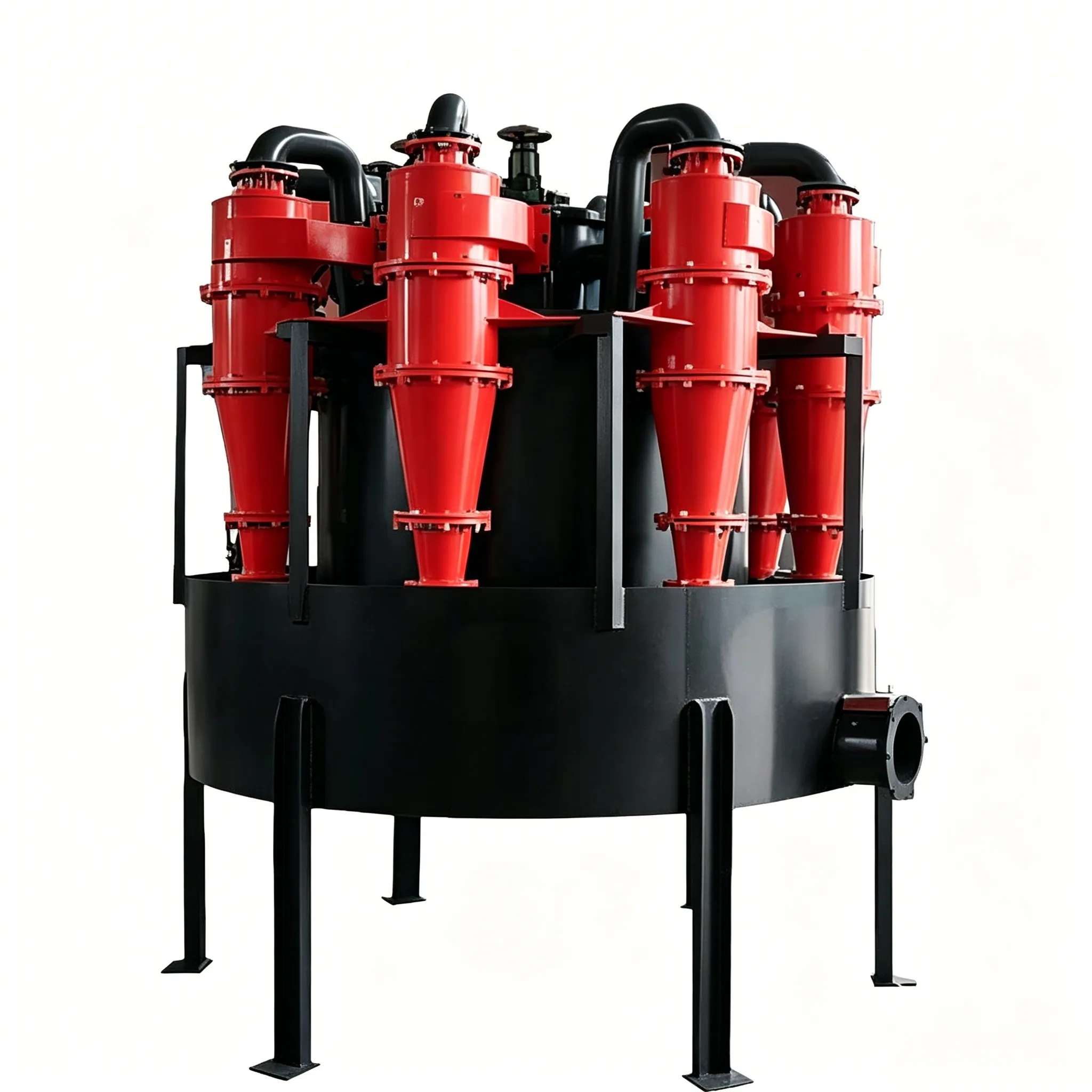
Figure 11-7 Hidrociclón
1—Feed pipe (feed inlet); 2—Cylindrical shell (cylindrical section);3—Overflow pipe (vortex finder);
4—Conical shell (conical section);5—Spigot (underflow outlet / sand outlet);6—Overflow conduit (overflow hose / discharge pipe)
Parameter Selection for Hydrocyclone
There are many parameters related to the hydrocyclone, including structural parameters, process operating parameters, and feed property parameters. These parameters are often interrelated and mutually constraining, making them difficult to adjust and control. The main parameters are briefly described as follows.
(1) Diameter and height of the cylindrical shell. The diameter of the cylindrical shell is the main specification of the hydrocyclone and has a certain relationship with the dimensions of other components. Increasing the diameter increases the processing capacity but coarsens the overflow particle size, and vice versa. For fine particle classification and increased throughput, it is common to use multiple small hydrocyclones connected in parallel as a group.
(2) Height of the cylindrical shell. The height of the cylindrical shell affects the residence time of the pulp in the hydrocyclone and the classification efficiency. However, too high or too low is not desirable. Generally, it is 0.6–1.0 times the diameter.
(3) Feed inlet diameter. The feed inlet diameter is usually 0.08–0.25 times the hydrocyclone diameter. A larger value increases throughput but reduces classification efficiency. The feed inlet is often rectangular in shape.
(4) Overflow pipe diameter. Generally, the overflow pipe diameter is 0.1–0.4 times the hydrocyclone diameter. It can be used to adjust the relative yield of overflow and underflow. Increasing the overflow pipe diameter increases the overflow volume, coarsens the overflow particle size, reduces fines in the underflow, and increases the underflow concentration.
(5) Spigot diameter. Increasing the spigot diameter reduces the overflow volume, makes the overflow finer, increases the underflow volume, lowers the underflow concentration, and increases the amount of fines in the underflow, but has no significant effect on throughput. Reducing the spigot diameter decreases the underflow discharge volume and may cause “coarse particles escaping into the overflow.” If the spigot diameter is too small, coarse particles will accumulate at the cone apex, leading to blockage. A suitable spigot diameter should allow the underflow to discharge in a slight umbrella shape with an included angle of 40°–70°. The ratio of spigot diameter to overflow pipe diameter is generally 0.4–0.8.
(6) Insertion depth of the overflow pipe. Too shallow an insertion allows coarse particles to enter the overflow without sufficient classification under centrifugal force; too deep an insertion allows coarse particles from the bottom to enter the overflow. Both reduce classification efficiency. The insertion depth of the overflow pipe should generally be 0.7–0.8 times the height of the cylindrical shell.
(7) Cone angle of the conical shell. Increasing the cone angle reduces the equipment height and increases the average radial flow velocity of the pulp. At the same time, the greater flow resistance of the cone increases the upward flow velocity of the pulp, resulting in a coarser overflow particle size. Therefore, a large cone angle (30°–60°) is used for coarse separation, a small cone angle (15°–30°) for fine separation, and an even smaller cone angle (10°–15°) for desliming.
(8) Feed pressure. The commonly used feed pressure is 0.05–0.16 MPa. Feed pressure is directly related to throughput and separation particle size. Increasing the feed pressure can reduce the separation size and increase throughput, but it significantly increases power consumption and equipment wear. During normal operation, the feed pressure should be kept stable.
(9) Pulp properties. These mainly refer to ore density, particle size, and pulp concentration. The higher the ore density, the finer the separation size. When the pulp concentration is high and the slime content is high, the viscosity and density increase, increasing the resistance to particle movement and resulting in a coarser separation size. Conversely, the separation size becomes finer. The suitable pulp concentration is generally determined by experiments based on specific conditions.
From the above parameters, it can be seen that the main factors affecting the performance of a hydrocyclone are its own structural parameters. This requires a variety of hydrocyclone structures to suit different working conditions and applications. To this end, China has developed and produced many series of hydrocyclones according to different user requirements. Some manufacturers can also design and manufacture various types of hydrocyclones for specific uses. The most widely used hydrocyclones and hydrocyclone clusters are shown in Table 11-6 and Table 11-7.
Table 11-6 Technical parameters of hydrocyclones
| Modelo | Inner dia. /mm | Overflow pipe dia. /mm | Spigot dia. /mm | Cone angle /(°) | Max feed size /mm | Inlet pressure /MPa | Capacity /m³·h⁻¹ | Separation size /mm | Weight /kg |
|---|---|---|---|---|---|---|---|---|---|
| FX850 | 850 | 260–340 | 80–200 | 20 | 22 | 0.03–0.4 | 600–850 | 100–350 | 2600 |
| FX710 | 710 | 220–300 | 60–180 | 20 | 16 | 0.03–0.4 | 400–550 | 74–250 | 1245 |
| FX660 | 660 | 150–260 | 60–160 | 20 | 16 | 0.03–0.4 | 250–420 | 74–220 | 950 |
| FX610 | 610 | 140–220 | 40–120 | 20 | 12 | 0.03–0.4 | 200–260 | 74–200 | 670 |
| FX500 | 500 | 100–200 | 35–115 | 25,20,15 | 10 | 0.03–0.4 | 140–220 | 74–200 | 416,490,556 |
| FX350 | 350 | 70–135 | 30–85 | 20,15 | 7,6 | 0.03–0.4 | 85–150 | 50–150 | 135,155,230 |
| FX300 | 300 | 65–135 | 16–60 | 20,15 | 5 | 0.05–0.4 | 45–90 | 40–150 | 88,169 |
| FX250 | 250 | 45–120 | 15–60 | 20,15,10 | 3 | 0.05–0.4 | 40–80 | 30–100 | 63,120,123 |
| FX200 | 200 | 40–85 | 15–40 | 20,15 | 2 | 0.05–0.4 | 25–40 | 30–100 | 36,64 |
| FX150 | 150 | 25–50 | 8–30 | 20,15,8 | 1.5 | 0.05–0.4 | 15–30 | 20–74 | 22,20,60 |
| FX125 | 125 | 25–40 | 8–26 | 17,8 | 1 | 0.05–0.4 | 8–15 | 20–100 | 10,12 |
| FX100 | 100 | 20–40 | 6–22 | 20,15,8 | 1 | 0.05–0.4 | 8–15 | 10–100 | 8,5,6 |
| FX75 | 75 | 15–20 | 3–13 | 15,7 | 0.6 | 0.1–0.5 | 3–7 | 5–74 | 4,7 |
| FX50 | 50 | 11–18 | 3–12 | 15,6 | 0.3 | 0.1–0.5 | 1.5–3 | 5–74 | 2,2.5 |
| FX25 | 25 | 5-8 | 2–5 | 5,3 | 0.2 | 0.1–0.5 | 0.3–1 | 2–10 | 0.8,1.4 |
| FX10 | 10 | 2–4 | 1–2 | 4 | 0.1 | 0.1–0.6 | 0.05–0.1 | 1–5 | 0.5 |
Table 11-7 Technical parameters of hydrocyclone clusters
| Modelo | Feed main pipe dia. /mm | Overflow main pipe dia. /mm | Spigot main pipe dia. /mm | Feed pressure /MPa | Max feed size /mm | Separation size /mm | Capacity /m³·h⁻¹ |
|---|---|---|---|---|---|---|---|
| FX710×10 | DN850 | DN950 | DN700 | 0.03–0.15 | 16 | 74–250 | 2000–5500 |
| FX710×2 | DN300 | DN400 | DN360 | 0.03–0.15 | 16 | 74–250 | 400–1100 |
| FX660×16 | DN800 | DN1100 | DN700 | 0.03–0.15 | 16 | 74–220 | 2000–6720 |
| FX660×4 | DN350 | DN400 | DN350 | 0.03–0.15 | 16 | 74–220 | 500–1680 |
| FX610×6 | DN300 | DN450 | DN300 | 0.03–0.15 | 12 | 74–200 | 600–1560 |
| FX500×8 | DN400 | DN500 | DN350 | 0.03–0.15 | 10 | 74–200 | 560–1760 |
| FX350×18 | DN350 | DN450 | DN350 | 0.08–0.20 | 6 | 50–150 | 340–1200 |
| FX350×8 | DN250 | DN350 | DN300 | 0.08–0.20 | 6 | 50–150 | 340–1200 |
| FX300×16 | DN300 | DN350 | DN300 | 0.08–0.20 | 5 | 40–150 | 90–360 |
| FX300×4 | DN150 | DN250 | DN250 | 0.08–0.20 | 5 | 40–150 | 90–360 |
| FX250×12 | DN250 | DN300 | DN300 | 0.08–0.20 | 3 | 30–100 | 240–960 |
| FX150×24 | DN300 | DN350 | DN300 | 0.10–0.30 | 1.5 | 20–74 | 180–720 |
| FX100×16 | DN200 | DN300 | DN200 | 0.10–0.30 | 1.0 | 20–74 | 64–240 |
| FX75×25 | DN150 | DN250 | DN150 | 0.10–0.30 | 0.6 | 20–74 | 36–175 |


