
Initially, the SF and JF (JJF) flotation machines were combined into a joint unit. The SF flotation machine was used as the first cell of each bank to provide self‑priming of the pulp, thereby eliminating the need for a stepped layout and froth pumps for middling return.
Initially, the SF and JF (JJF) flotation machines were combined into a joint unit. The SF flotation machine was used as the first cell of each bank to provide self‑priming of the pulp, thereby eliminating the need for a stepped layout and froth pumps for middling return. The JJF flotation machine was used as the direct‑flow cell following the first cell to achieve high separation performance. In this way, the advantages of both machines were fully utilized. Later, the SF flotation machine was also used alone, with quite good results.
(1) Structure and working principle
The structure of the SF flotation machine is shown in Figure 12‑6. It mainly consists of the cell tank, the main shaft assembly with the impeller, the electric motor, the scraper and its drive, etc. For models with a volume larger than 10 m³, a draft tube and a false bottom are provided.
During operation of the SF flotation machine, the electric motor drives the main shaft via a V‑belt, causing the impeller at the lower end to rotate. The main characteristic of this flotation machine is embodied in its impeller. The impeller has backward‑inclined double‑sided blades, which enable double circulation of the pulp inside the cell. When the impeller rotates, the pulp in the upper and lower impeller chambers is thrown outward by the centrifugal force generated by the upper and lower blades (i.e., main and auxiliary blades), creating negative pressure zones in both chambers. Meanwhile, pulp from above the cover plate is drawn into the upper impeller chamber through the circulation holes in the cover plate, forming the upper pulp circulation. The pulp discharged from the lower impeller chamber has a higher density than the three‑phase mixture discharged from the upper blades; therefore, it has a larger centrifugal force and a slower decay of motion velocity. It exerts an additional driving force on the three‑phase mixture discharged by the upper blades, increasing its centrifugal force and thereby enhancing the vacuum in the upper impeller chamber, which assists air suction. When the lower blades throw pulp outward, the pulp below them replenishes toward the centre, thus forming the lower pulp circulation. Air is drawn through the air intake pipe and the central tube into the upper impeller chamber, where it mixes with the drawn‑in pulp to generate a large number of fine bubbles. After flow stabilization by the cover plate, the bubbles are uniformly dispersed throughout the cell, forming mineralized bubbles. The mineralized bubbles rise to the froth layer and are scraped out as froth product.

Figure 12‑6 SF flotation machine
1—Belt pulley; 2—Air suction pipe; 3—Central tube; 4—Main shaft; 5—Cell tank;
6—Cover plate (stator); 7—Impeller; 8—Draft tube; 9—False bottom;
10—Upper blade; 11—Lower blade; 12—Impeller disc
(2) Main features
According to process requirements, the operational units can be configured as needed. For the Type 4 flotation machine, each bank has a maximum of 8 cells; for Type 8 and Type 10, each bank has a maximum of 6 cells; for Type 20, each bank has a maximum of 5 cells.

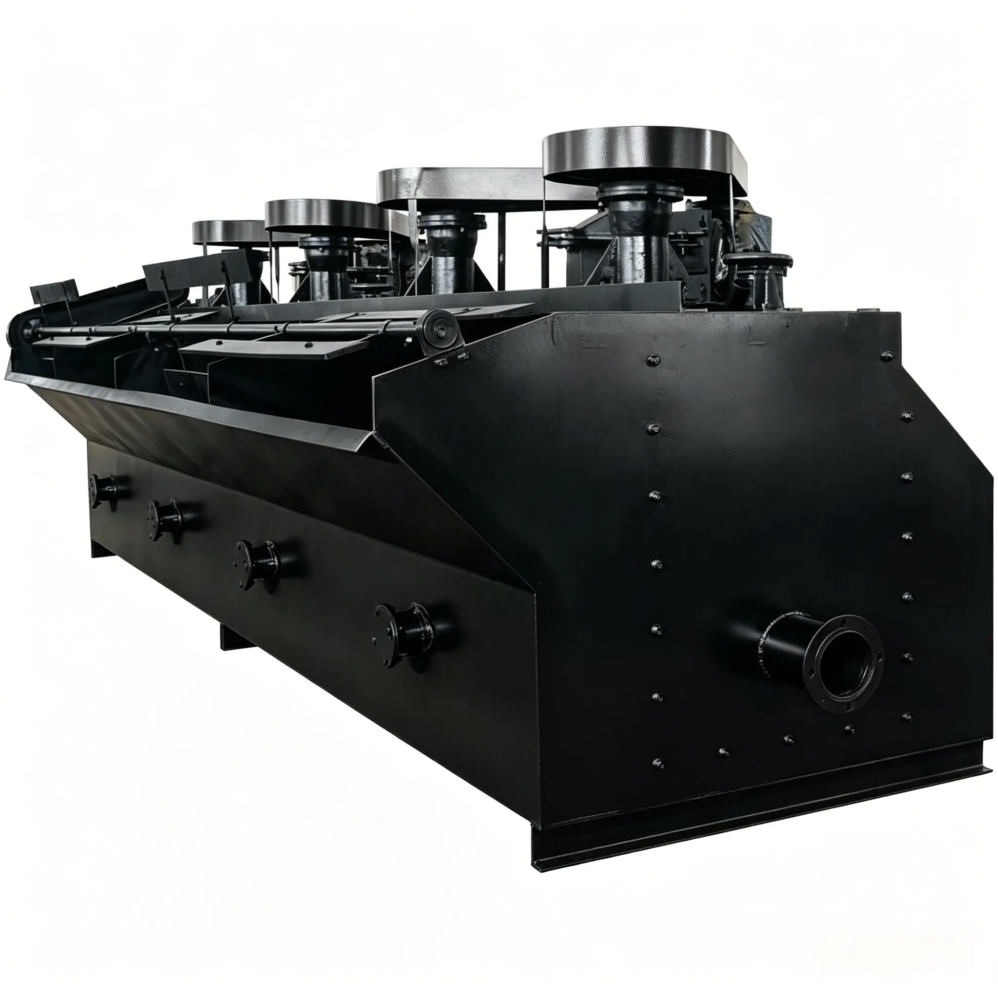
Figure 12‑7 BF flotation machine
1—Scraper; 2—Bearing housing; 3—Electric motor; 4—Central tube; 5—Air suction pipe;
6—Cell tank; 7—Main shaft; 8—Stator; 9—Impeller
The user must provide the flotation machine flow configuration drawing when placing an order. The following items shall be indicated on the configuration drawing:
The SF and JJF flotation machines and their technical specifications are listed in Table 12‑5.
The BF flotation machine is an improved version of the SF flotation machine (Figure 12‑7). In 1994, it was recommended as an excellent energy‑saving product, and in 1999 it received a National Invention Patent of China. Its features are as follows:
The technical parameters of the BF flotation machine are listed in Table 12‑6.
Table 12-5 Technical performance of SF and JF type flotation machines
| type Number | SF-0.15 | SF-0.37 | SF-1.2 | SF-4 | SF-8 | SF-10 | SF-20 | JJF-4 | JJF-8 | JJF-10 | JJF-20 | |
| Effective volume of the tank / m³ | 0.15 | 0.37 | 1.2 | 4 | 8 | 10 | 20 | 4 | 8 | 10 | 20 | |
| Tank Dimensions(Length × Width × Height) /mm×mm×mm | 500×500 ×600 | 700×700 ×750 | 1100×1100×1100 | 1850×2050×1200 | 2200×2900 ×1400 | 2200×2900 ×1700 | 2850×3800 ×2000 | 1600×2150×1250 | 2200×2900 ×1400 | 2200×2900 ×1700 | 2850×3800 ×2000 | |
| Production capacity(by slurry volume) /m³ ·min ⁻ ¹ | 0.06~0.18 | 0.2~0.4 | 0.6-1.2 | 2~4 | 4~8 | 5~10 | 5~20 | 2~4 | 4-8 | 5-10 | 5~20 | |
| Inhalation volume/m³ ·m ⁻ ² ·min¹ | 0.8~1.0 | 0.8-1.0 | 1-1.2 | 0.9-1.0 | 0.9-1.0 | 0.9-1.0 | 0.9~1.0 | 0.9~1.0 | 0.9-1.0 | 0.9-1.0 | ||
| spindleelectric motor | modelo | Y100L-6 | Y90L-4 | Y132M ₂ -6 | Y200L-8 | Y250M-8 | Y250M-8 | Y250M-8 | Y160L-6 | Y200L6 | Y200L ₂ | 6Y280S-8 |
| Power/kW | 1.5 | 1.5 | 5.5 | 15 | 30 | 30 | 30×2 | 11 | twenty two | twenty two | 37 | |
| rotational speed/r ·min-1 | 940 | 1400 | 960 | 730 | 730 | 730 | 730 | 970 | 970 | 970 | 730 | |
| impeller | Diameter/mm | 200 | 296 | 650 | 760 | 760 | 760 | 410 | 540 | 540 | 700 | |
| Height/mm | 57 | 80 | 131 | 186 | 186 | 186 | 410 | 540 | 540 | 700 | ||
| rotational speed/r ·min-¹ | 536 | 386 | 220 | 191 | 191 | 191 | 305 | 233 | 233 | 180 | ||
| Circular speed /m ·s¹ | 5.6 | 6.0 | 7.3 | 7.5 | 7.5 | 7.5 | 6.55 | 6.6 | 6.6 | 6.6 | ||
| scraper electric motivation | modelo | Y801-4 | Y801-4 | Y90S-4 | Y100L-6 | Y100L-6 | Y100L-6 | Y100L-6 | Y100L-6 | Y100L-6 | Y100L-6 | Y100L-6 |
| Power/kW | 0.55 | 0.55 | 1.1 | 1.5 | 1.5 | 1.5 | 1.5 | 1.5 | 1.5 | 1.5 | 1.5 | |
Table 12‑6 Technical parameters of BF flotation machine
| Modelo | Cell volume (m³) | Internal dimensions (L×W×H) (m×m×m) | Air suction volume (m³·m⁻²·min⁻¹) | Installed power (kW) | Motor model | Capacity (m³·min⁻¹) | Weight per cell (kg) |
|---|---|---|---|---|---|---|---|
| BF‑0.15 | 0.15 | 0.55×0.55×0.6 | 0.9–1.05 | 2.2 | Y112M‑6 | 0.06–0.16 | 270 |
| BF‑0.25 | 0.25 | 0.65×0.6×0.7 | 0.9–1.05 | 1.5 | Y100L‑6 | 0.12–0.28 | 370 |
| BF‑0.37 | 0.37 | 0.74×0.74×0.75 | 0.9–1.05 | 1.5 | Y90L‑4 | 0.2–0.4 | 470 |
| BF‑0.65 | 0.65 | 0.85×0.95×0.9 | 0.9–1.10 | 3.0 | Y132S‑6 | 0.3–0.7 | 932 |
| BF‑1.2 | 1.2 | 1.05×1.15×1.10 | 1.0–1.10 | 5.5 / 4.0 | Y132M₂‑6 / Y132M₁‑6 | 0.6–1.2 | 1370 |
| BF‑2.0 | 2.0 | 1.40×1.45×1.12 | 1.0–1.10 | 7.5 | Y160M‑6 | 1.0–2.0 | 1750 |
| BF‑2.8 | 2.8 | 1.65×1.65×1.15 | 0.9–1.10 | 11 | Y180L‑8 | 1.4–3.0 | 2130 |
| BF‑4.0 | 4.0 | 1.9×2.0×1.2 | 0.9–1.10 | 15 | Y200L‑8 | 2–4 | 2585 |
| BF‑6.0 | 6.0 | 2.2×2.35×1.3 | 0.9–1.10 | 18.5 | Y225S‑8 | 3–6 | 3300 |
| BF‑8.0 | 8.0 | 2.25×2.85×1.4 | 0.9–1.10 | 22 / 30 | Y225M‑8 / Y250M‑8 | 4–8 | 4130 |
| BF‑10 | 10 | 2.25×2.85×1.7 | 0.9–1.10 | 22 / 30 | Y225M‑8 / Y250M‑8 | 5–10 | 4660 |
| BF‑16 | 16 | 2.85×3.8×1.7 | 0.9–1.10 | 37 / 45 | Y280S‑8 / Y280M‑8 | 8–16 | 8320 |
| BF‑20 | 20 | 2.85×3.8×2.0 | 0.9–1.10 | 37 / 45 | Y280S‑8 / Y280M‑8 | 10–20 | 8670 |
| BF‑24 | 24 | 3.15×4.15×2.0 | 0.9–1.10 | 45 | Y280M‑8 | 12–24 | 8970 |


