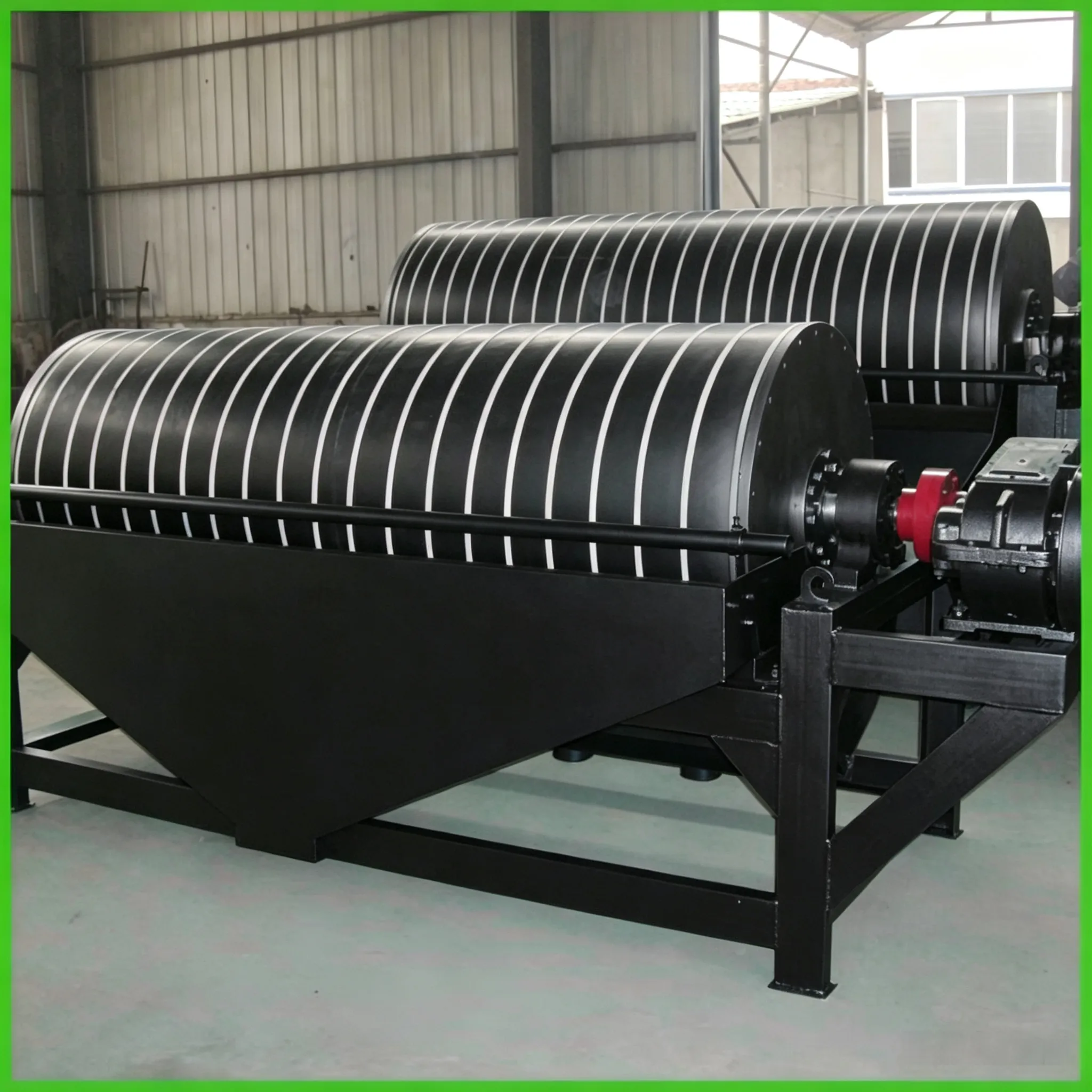
Costruzione di separatori a tamburo con magneti permanenti
I separatori a tamburo con magneti permanenti sono ampiamente utilizzati per la lavorazione del minerale di magnetite, dei granuli grossolani…


Liners with a flat working surface or with cast patterns are both called flat liners. Those with cast patterns are also referred to as patterned flat liners. Flat liners provide low friction to the grinding media, causing the media to slide more on their surface, thus enhancing the attrition (grinding) action on the material. They are usually used in combination with corrugated liners in the fine‑grinding compartment.
Corrugated liners have a wave‑shaped working surface. A liner with only one wave crest is called a single‑wave or large‑wave corrugated liner; one with two crests is called a double‑wave or medium‑wave corrugated liner; and one with multiple crests is called a small‑wave corrugated liner or simply a corrugated liner. The ball‑lifting height of single‑wave and double‑wave liners is lower than that of lifting bar liners. When the wave crest is on the rising side, it lifts balls upward; when on the falling side, it throws balls downward, making it suitable for the rod compartment of rod mills. Small‑wave corrugated liners have small crests and pitches, with low lifting height, making them suitable for fine‑grinding compartments and coal mills.
Ribbed liners are flat liners with a semi‑circular or trapezoidal rib cast on the working surface. The rib lifts the grinding media, giving them a stronger impact action. They are used in the first compartment, but are not suitable for rod mills or the rod compartment of rod‑ball mills. Because the ribs wear easily, mill output becomes unstable, so ribbed liners are gradually being replaced by stepped liners.
Lifting bar liners consist of a flat liner and lifting bars. The bars have bolt holes, and bolts pass through these holes to fix the bars and the liner (which has no holes) onto the shell inner wall. The bars protrude above the liner surface, increasing the lifting effect on the grinding media and giving the media greater impact and grinding force. They are suitable for the first compartment, especially when the feed material is coarse and hard. In compartments with lifting bar liners, wear on both balls and liners is more severe, and they are not recommended for mills with increased rotational speed.
Stepped liners, also called ship‑rudder liners, have an inclined working surface. After installation, they form many steps and are suitable for the head compartment of tube mills. Such liners increase the thrust on the grinding media. They provide uniform lifting height for balls in the same layer; they have a strong restraining effect on the balls, preventing sliding and wear between different layers of media, and reducing sliding and wear between the outermost media and the liners. In addition, the liner surface wears evenly and the shape change after wear is not obvious. The thin end of a stepped liner faces the direction of rotation when the mill is running.
Hemispherical liners have half‑sphere protrusions on the working surface, arranged in a staggered (triangular) pattern. They prevent balls from sliding along the shell and avoid the formation of annular grooves due to wear, thereby reducing consumption of both grinding media and liners. They are suitable for crushing compartments.
Conical classifying liners, also called taper classifying liners, form a segmented conical grinding chamber along the compartment after installation. The tangent of the inclination angle of such liners is greater than or equal to the equivalent rolling friction coefficient of the balls. Under the effect of the inclination, balls roll toward the mill head along the conical surface, and the larger the ball diameter, the greater its forward rolling, thus achieving positive classification of steel balls. Common types include the Karman conical classifying liner, the Schlegelton conical classifying liner, and the FLS‑type conical classifying liner. The first has a flat conical working surface, the second combines a flat conical surface with an arc conical surface, and the last is assembled from two flat liners and one Karman conical classifying liner.
This type of liner can be used in open‑circuit as well as closed‑circuit mills; for raw mills as well as cement mills; for dry process as well as wet process; and for classification of steel balls as well as mixed ball‑cylpeb media. Such liners are generally only used in the fine‑grinding compartment of medium‑long mills. In a medium‑long mill with a small L/D ratio, when a pre‑crushing process is adopted and the feed particle size d₈₀ is reduced to about 3 mm, the entire mill effectively becomes a fine‑grinding compartment. In this case, the intermediate diaphragm can be removed and conical classifying liners installed throughout the whole mill to increase effective volume and reduce ventilation resistance, thereby further increasing output. According to published reports, after installing conical classifying liners in tube mills, output increases by 5%–15% while product fineness remains essentially unchanged, and unit power consumption drops by 10%–18%. Disadvantages of conical classifying liners: effective volume of the mill is reduced; the precision of the cone inclination angle is high (angle errors affect classification performance), making manufacturing difficult; and installation is rather troublesome.
Angle spiral liners, also called CZ liners, are mostly used in the second compartment. After installation, they form a square‑tapered surface with four rounded corners inside the compartment, hence they are also called round‑corner square liners. The rounded‑square corners of adjacent rings are offset by an angle relative to each other, and form a certain helix angle axially (generally 12°–22.5° for cement mills, and about 36° for producing high‑grade cement). The rotation direction of the liners is opposite to that of the mill shell. Thus, along the entire mill length, the grinding chamber forms a continuous four‑start helix. The spiral surfaces at the rounded corners have a strong gripping effect on small balls, pushing them toward the discharge end; at the same time, the thrust from the helix angle pushes large balls toward the feed end. Therefore, this liner achieves good positive ball classification, even better than conical classifying liners.
The following effects are observed after installing this liner:
① The radius of rotation for each layer of balls changes instantaneously, causing variations in the falling height, falling point, and impact kinetic energy of balls in the same layer, thereby enhancing the mixing and penetration between media and material.
② The different rotational and falling speeds of balls and material create intense friction between the “ball‑material curtain” surfaces of adjacent liners.
③ The thrust of the inner spiral surfaces generates local axial eddy currents in the ball regions of the same diameter zone, intensifying the grinding action.
④ It provides good positive classification of balls. Over‑grinding is significantly reduced (particularly noticeable in open‑circuit mills); mill operation is more stable; and the service life of the transmission is extended.
After installing this liner, the effective volume of the compartment is reduced by 10%–15% compared to ordinary liners. It generally works well on large mills (above φ3m). Installation and removal of this liner are difficult. When using this liner, the ball charge should be appropriately reduced and the average ball diameter in the first compartment increased; the moisture content of the feed material must also be strictly controlled.
Hyperboloid classifying liners combine the advantages of both classifying liners and stepped liners. Axially they resemble classifying liners, enabling rational classification of steel balls along the axis. As balls roll and slide along the curved surface of the liner, due to the different energy levels of large and small balls, smaller balls are pushed axially toward the mill tail, achieving automatic ball classification. The curved surface forms an intermittent spiral line inside the mill, applying thrust to the material toward the mill tail, thereby accelerating material flow and effectively reducing over‑grinding. Circumferentially, the liner has a stepped configuration with a certain lifting inclination, ensuring that falling balls do not impact bare liners, thus reducing liner damage and wear. Compared with ordinary liners, this liner saves about 10% energy.
Spiral grooved liners have grooved working surfaces with an inclination angle (less than 12°). After installation, the grinding chamber surface resembles a continuous multi‑start helix (with the spiral direction the same as the mill rotation). Used in fine‑grinding compartments, these liners combine the function of grooved liners with the ability to achieve rational axial classification of steel balls.
Within the same compartment, several types of liners with different lifting/friction coefficients on their working surfaces are combined so that the average lifting/friction coefficient of each ring decreases progressively along the material flow direction. This achieves the purpose of reducing the liner’s restraining and lifting capacity toward the discharge end, pushing larger balls toward the high‑energy region, and realising automatic classification of the grinding media. In Germany (formerly FRG), lifting bar liners with different bar heights were combined to form classifying liners, increasing mill output by 5%–10%. The practice involved arranging the lifting bars in the coarse‑grinding compartment into five rows: first row – bar height 55 mm (16 bars), second row – 45 mm (16 bars), third row – 45 mm (8 bars), fourth row – 30 mm (8 bars), fifth row – 30 mm (4 bars), and the sixth row as flat liners without bars. Huaxin Cement Plant arranged stepped liners and flat liners in an alternating pattern so that the energy transferred from the liners to the balls decreased along the material flow direction, eliminating reverse classification of balls, with output increasing by 4%–7% and consumption of both liners and balls reduced.
Double‑helix shaped classifying liners are round‑corner polygonal liners with inclined ribs arranged at different densities. Both the round‑corner polygonal profiles and the inclined ribs are arranged in a double‑helix pattern axially, with the rib density decreasing along the material flow direction. Such liners transfer different energy levels through the liner surface and also generate axial thrust from the helix angle of the liners and ribs. This enables positive classification of steel cylpebs in the cylpeb compartment, positive classification of balls in the ball compartment, and positive classification of mixed media in a combined ball‑cylpeb compartment. Trials on tube mills of φ2.2 m and below have shown output increases of 5%–15% and power consumption reductions of 8%–15%. In addition, because these liners are arranged alternately along the mill length, the load is discharged alternately, enhancing the shearing action between steel cylpebs and material, and significantly improving product fineness while output remains unchanged.
Grooved liners have multiple grooves on the working surface of each individual liner. After installation, they form circumferential grooves, hence they are also called ring‑groove liners.
The grooves on grooved liners are designed to allow steel balls to pack in a hexagonal arrangement on the liner surface. Under this packing form, the balls have a higher coordination number and greater density, resulting in a higher probability of effective collisions between balls. In addition, the contact between balls and liners changes from point contact (as with flat or raised liners) to 120° line contact, greatly increasing the grinding area. Under such contact conditions, the material between balls and liners does not splash away as easily as with flat or raised liners, but instead forms a material layer that does not readily detach, allowing full grinding within the grooves, thus achieving high grinding efficiency.
Grooved liners have three forms: ring grooves, spiral grooves, and activated liners. Depending on mill operating conditions, they can achieve rational ball classification and improve grinding performance.
Additional benefits of using grooved liners include:
① The angle of separation of grinding media on corrugated liners is 55°, while on grooved liners it is 60°. Because the separation angle increases, the mill torque decreases; combined with the fact that grooved liners are about 10% lighter than ordinary liners, the required mill power drops by about 20%.
② There is always a layer of material between the balls and the liners, so balls do not come into direct contact with the liners. Not only are wear rates of both balls and liners greatly reduced, but grinding noise is also significantly lowered, and the heat generated during grinding is 6%–7% lower than with ordinary liners.
③ Because the separation angle of balls on grooved liners is larger, and the liners do not accelerate the ball throw, when balls fall they land in the toe zone without directly impacting bare liners. Thus, shell liners and bolts are less prone to breakage, maintenance work is reduced, and operating noise and grinding temperatures are lower.
④ The grooves wear evenly in all parts, so the groove shape remains unchanged throughout the entire service life from installation to replacement. Consequently, grinding and crushing efficiency does not deteriorate due to liner wear.
⑤ The lifting height of grinding media on grooved liners is lower and more uniform than on stepped or ribbed liners. As a result, the load centre of gravity shifts toward the centre, reducing drive power, mill vibration, and damage to transmission gears.
⑥ On small mills, after grooved liners wear, the effective internal diameter increases significantly. At that point, appropriately increasing the grinding media load can boost mill output.
⑦ Fewer liner types, lighter weight, and easy installation – they can be fixed with bolts or by wedging. Owing to the above factors, installing grooved liners can increase output by 7%–20%, reduce power consumption by 8%–20%, reduce ball consumption by 15%–40%, extend liner life nearly threefold, and lower noise by 4–6 dB.
Conditions for using grooved liners:
① Balls must be used as grinding media in the compartment. In closed‑circuit mills, every compartment can be equipped with grooved liners; in open‑circuit two‑compartment mills, grooved liners are generally installed only in the first compartment.
② The material of grooved liners is generally high‑chromium cast iron, medium‑carbon alloy steel, low‑chromium cast iron, or other high‑hardness wear‑resistant materials, depending on mill diameter and compartment type. For larger mills, liners in the coarse‑grinding compartment should have higher toughness.
③ Grooved liners perform even better at higher mill speeds.
④ The total moisture content of the mill feed should be less than 2% to avoid material sticking in the grooves.
⑤ The d₈₀ of the feed material should be ≤ 20 mm.
⑥ The groove dimensions are designed according to the diameter of the largest balls. To highlight the groove effect, it is advisable to use larger balls and avoid multi‑stage ball gradations. The cement plant of Zhengzhou Aluminium Plant changed from four‑stage ball gradation to two‑stage large balls each at 50%; Changlv Cement Plant adopted a two‑stage gradation with small balls filling the gaps between the largest balls – both achieved good results. When small balls are used to fill the gaps between large balls, the small ball diameter d₁ = 0.414d (where d is the large ball diameter, mm). The small ball charge should be 4%–5% of the total ball charge in that compartment.

 English English
 Spanish
 Russian
 Arabic
 Swahili
 French
 Turkish
 Portuguese
 Korean
 Japanese
 German
 Italian