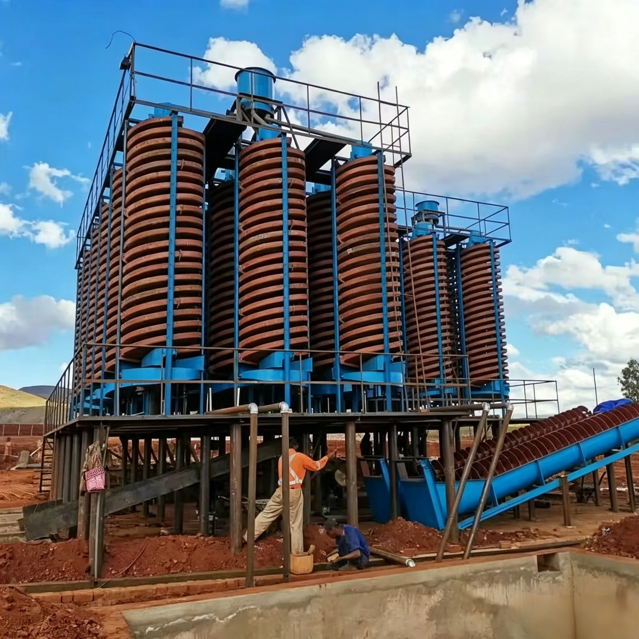
スパイラルシュート
Spiral Chute – High-Efficiency, Low-Cost Gravity Concentrator Product Overview The spiral chute…


In the past, toughening and reinforcing modification of polypropylene (PP) commonly used rubber‐type elastomer blending, fiber reinforcement, or filler compounding. In recent years, both fundamental and applied research on filling various polymers with nano‑sized inorganic fillers has been carried out worldwide, including studies on PP filled with nanoscale particles such as montmorillonite, SiO₂, and TiO₂. However, because inorganic nanoparticles and polypropylene differ greatly in polarity and the nanoparticles have high surface energy, their compatibility is poor, and the nanoparticles tend to agglomerate severely, making it difficult to obtain composites with excellent performance. Ren Xiancheng et al. adopted appropriate surface pretreatment of nanoparticles and prepared high‑performance PP/nano‑CaCO₃ composites via melt blending.
14.4.1 Main raw materials
14.4.2 Process technology route
One‑step method: The surface‑pretreated CaCO₃ is directly blended with PP and compatibilizer B in a twin‑screw extruder.
Two‑step method: First, the surface‑pretreated CaCO₃ is compounded with compatibilizer B and a small amount of copolymer PP in a twin‑screw extruder to form a high‑concentration masterbatch; then the masterbatch is blended with PP.
14.4.3 Results and analysis
(1) Surface treatment of nano‑CaCO₃
According to the rigid inorganic particle toughening theory, one necessary condition for toughening by rigid inorganic particles is good interfacial bonding between the dispersed particles and the resin matrix. CaCO₃ filler has a highly polar surface, while PP is a non‑polar polymer, so their compatibility is poor. On the other hand, because nano‑sized CaCO₃ has high surface energy, it tends to agglomerate by itself, and it is even more difficult to disperse uniformly in a non‑polar polymer melt. Therefore, for the nano‑CaCO₃/PP system, proper surface treatment of CaCO₃ is essential to achieve a toughening effect.
Table 14‑6 shows the surface energy data of CaCO₃ and PP. It can be seen from Table 14‑6 that after treatment with surface treatment agent A, the surface energy of CaCO₃ particles decreases, mainly due to a significant reduction in the polar component. After treatment, the surface energy of the CaCO₃ particles approaches that of the PP matrix, which is beneficial for the dispersion of CaCO₃ particles in PP.

(2) Mechanical properties of PP/nano‑CaCO₃ composites
Figure 14‑11 shows the relationship between the tensile yield strength of the composites and the nano‑particle loading. The three curves correspond to three polypropylene matrix materials with different toughness levels. It can be seen from the figure that as the nano‑particle content increases, the tensile yield strength of the system initially rises, reaches a maximum, and then decreases. This is mainly because the surface treatment agent A used in the experiment has long alkyl chains that coat the CaCO₃ surface, forming a flexible interfacial layer. When a small amount of CaCO₃ is added, it mainly plays a reinforcing role. As the CaCO₃ content increases, the volume fraction of the flexible interfacial layer inside the composite increases. Under external stress, this flexible interfacial layer yields before the matrix does, leading to a reduction in the tensile strength of the material.
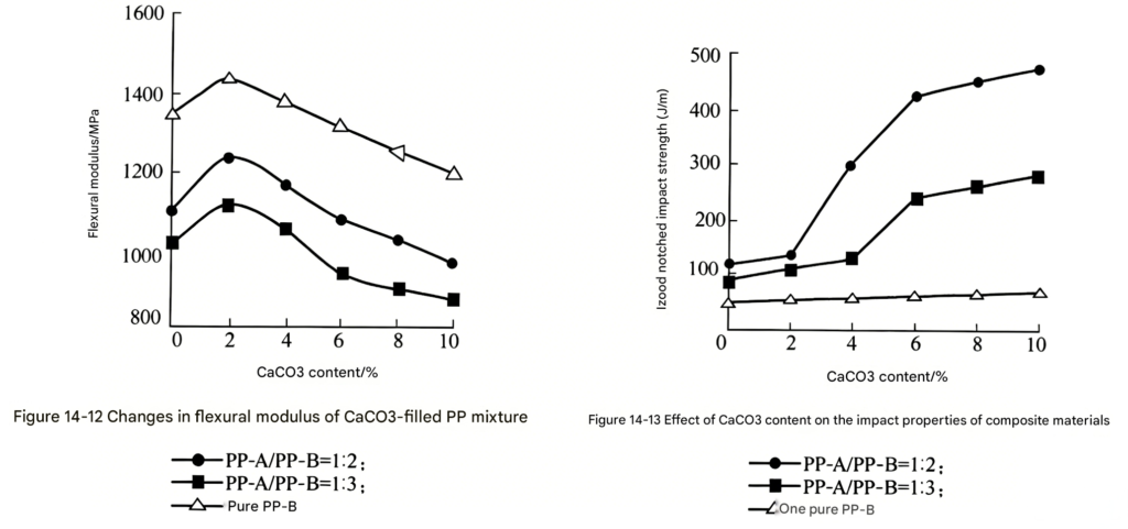
Figure 14‑12 shows the relationship between the flexural modulus of the composites and the nano‑particle loading. As can be seen from the figure, similar to the tensile properties, the flexural modulus of the system increases with increasing nano‑particle content, reaches a maximum, and then declines. This maximum also appears at about 2% loading. This trend is again attributed to the increased volume fraction of the flexible interfacial layer, which causes the material to yield at lower applied stresses.

Figure 14‑11 Effect of CaCO₃ filling on tensile strength
—◆— PP‑A/PP‑B = 1:3
—△— pure PP‑B
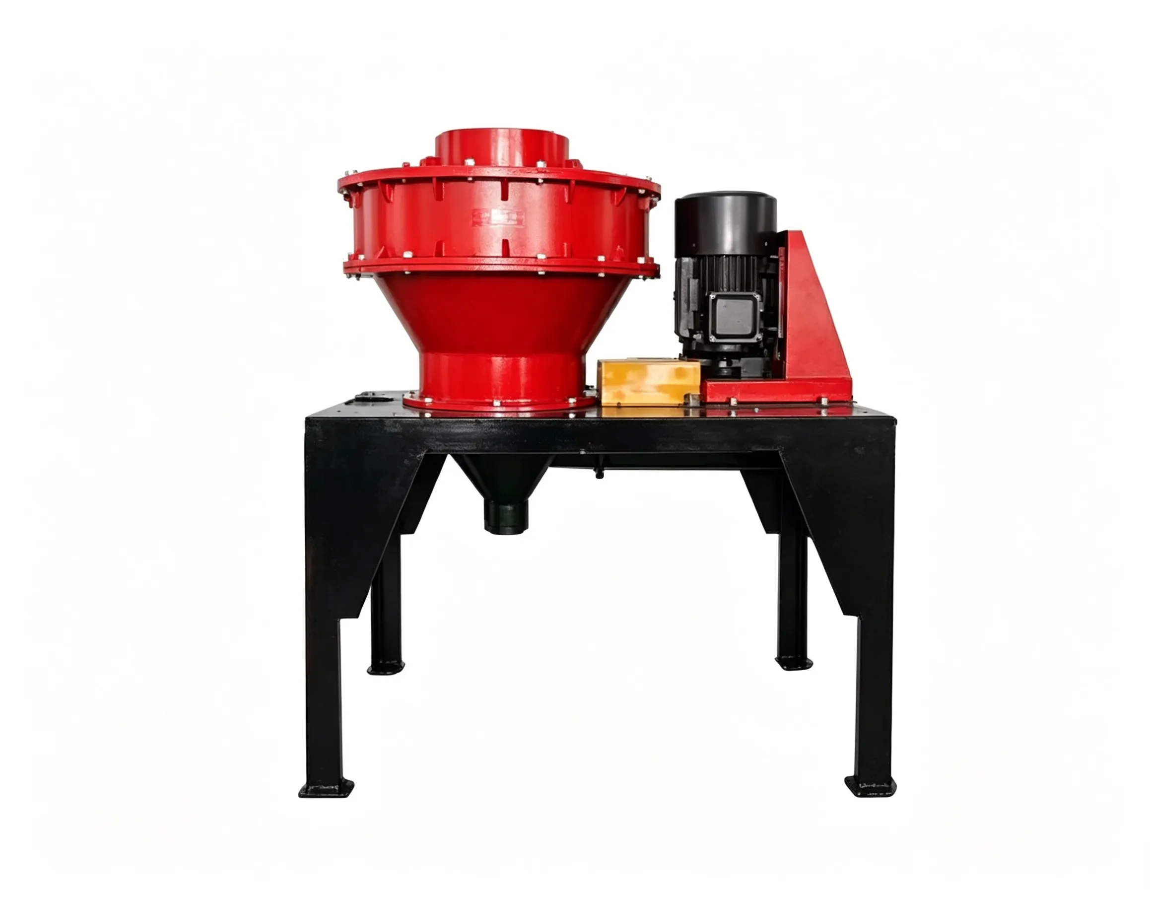
Figure 14‑13 shows the effect of nano‑CaCO₃ loading on the impact strength of the composites. It can be seen from the figure that with increasing nano‑particle content, the notched impact strength of all three systems increases to varying degrees. Among them, pure PP‑B, which has the poorest matrix toughness, shows the smallest improvement, while the other two systems with better matrix toughness exhibit a distinct brittle‑to‑ductile transition. This indicates that the toughening effect of nano‑CaCO₃ that is grinded by レイモンドミル on polypropylene is similar to that of rigid inorganic particles on polymers. Because the nanoparticles are much smaller in size, the critical content required to trigger the brittle‑to‑ductile transition is lower. A comparison of the three curves in the figure reveals that the better the toughness of the matrix, the lower the critical dispersed‑phase content needed for the brittle‑to‑ductile transition, and thus the higher the toughening efficiency.
(3) Comparison of mixing processes
Usually, when filling polymers with micron‑sized inorganic fillers, as long as the inorganic particles themselves have been surface‑treated, the mixing and dispersion process can generally be completed in a single pass through a twin‑screw extruder.
For nanoparticles, however, because of their high surface energy and relatively low content in the composite, achieving ideal dispersion is difficult with a single‑pass extrusion. We adopted a two‑step blending method in which a masterbatch is first prepared and then blended with the matrix, and compared its structure and properties with those of the one‑step method. Figure 14‑14 shows TEM images of the composites prepared by the two different mixing processes, and Table 14‑7 lists the corresponding mechanical properties. The nano‑CaCO₃ content was 5% by mass in all cases. It can be seen from Figure 14‑14 that in the material prepared by the one‑step method, the nanoparticles are rather unevenly dispersed, with many particles agglomerated. In contrast, in the composite prepared by the two‑step method, the particles are essentially monodispersed and appear generally uniform.

Figure 14‑14 TEM images of PP/CaCO₃ composites
Table 14‑7 Comparison of composite properties prepared by different processes
| Mechanical Property | One‑step method | Two‑step method |
|---|---|---|
| Tensile yield strength / MPa | 27.4 | 27.8 |
| Elongation at break / % | 320 | 450 |
| Flexural modulus / MPa | 1060 | 1120 |
| Izod notched impact strength / (J/m) | 130 | 348 |
As seen from the performance comparison in Table 14‑7, the properties of the material prepared by the one‑step method are essentially the same as those of the neat matrix, while the material prepared by the two‑step method exhibits significantly better properties than the matrix. At the same time, we also found in the experiments that the data variability in the mechanical property tests for the one‑step method is much larger than that for the two‑step method. This phenomenon can be understood as follows: the test samples prepared by the one‑step method contain many agglomerated particles, which do not contribute to improved mechanical properties, and many regions contain too few particles. Therefore, most specimens give measured values close to those of the neat polymer, and only a few areas happen to have a sufficient number of well‑dispersed particles, yielding impact strength values above the average.
(4) Observation of impact fracture surfaces of the composite system
Figure 14‑15 shows SEM images of the impact fracture surfaces of PP/CaCO₃ composites. For ductile fracture, impact energy dissipation mainly consists of matrix yielding deformation energy and crazing. For brittle fracture, the main energy dissipation pathway is cavitation‑crazing induced at the particle interfaces. On the fracture surface of the PP/CaCO₃ system shown in Figure 14‑15(a), distinct layered slip of the matrix in the impact direction is observed, along with fibrous deformation, indicating that the matrix has undergone yielding deformation. In contrast, the neat PP system shown in Figure 14‑15(b) shows almost no plastic deformation on the fracture surface. This indicates that the addition of nano‑CaCO₃ readily induces yielding deformation of the matrix, thereby increasing the dissipation of impact energy.
(5) DSC melting curve analysis
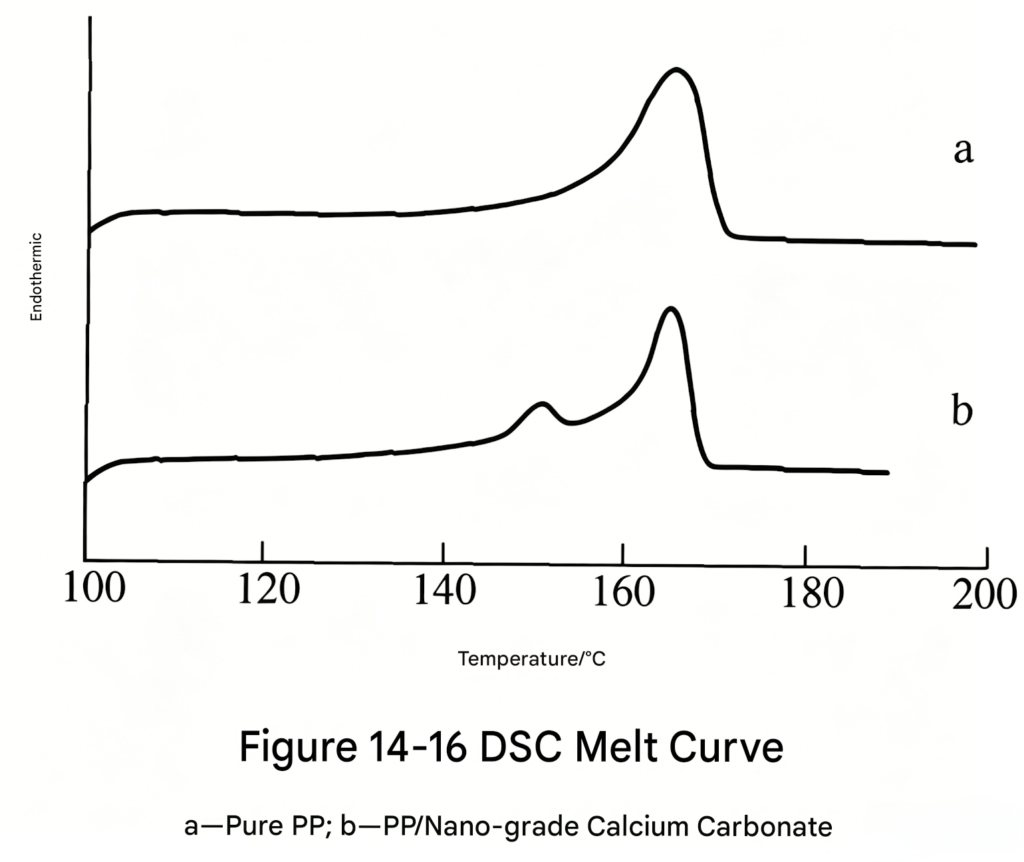
Figure 14‑16 shows the DSC melting curves of neat PP and the nano‑CaCO₃‑filled PP system. The samples were prepared by isothermal crystallization at 130 °C. From the curves, neat PP exhibits a typical α‑crystal melting peak at 165 °C, while the nano‑CaCO₃‑filled system exhibits not only the typical α‑crystal melting peak at 165 °C but also a small peak at 150.6 °C, corresponding to the β‑crystal form. The β‑crystal melting peak is much smaller than the α‑crystal melting peak, indicating that the addition of nano‑CaCO₃ causes polypropylene to grow both α‑crystals and a small amount of β‑crystals under these conditions.

Figure 14‑15 SEM images of impact test specimens
Literature has also reported that ultrafine yttrium oxide (Y₂O₃) with a particle size of 20 nm can alter the crystal form of polypropylene and increase the content of the β‑crystal, with the β‑crystal melting peak reaching about 3/4 of that of the α‑crystal. Based on this, we infer that nanoparticles have a significant induction effect on the β‑crystal crystallization process of polypropylene; the finer the particles, the higher their nucleation efficiency. Generally, an increase in β‑crystal content in polypropylene can markedly improve its impact resistance, so nanoparticle toughening modification of polypropylene is of great significance.
From the above discussion, the following conclusions can be drawn:
① After surface modification with a suitable modifier, nano‑CaCO₃ shows improved compatibility with polypropylene and reduced interfacial energy. Well‑dispersed PP/CaCO₃ nanocomposites can be prepared by a two‑step melt‑blending process, whereas the one‑step method fails to achieve ideal dispersion.
② Nano‑CaCO₃ can increase both the tensile yield strength and the flexural modulus of polypropylene, but these properties reach a maximum and then decrease with further filler loading. A brittle‑to‑ductile transition occurs at contents below 10%, with impact toughness increased by 3 to 4 times.
③ DSC melting curve analysis of the PP/nano‑CaCO₃ composites indicates that CaCO₃ has a notable induction effect on the β‑crystal crystallization of polypropylene, increasing the β‑crystal content and thereby improving the toughness of the PP matrix. At the same time, under impact loading, the nanoparticles induce yielding deformation of the matrix, changing the fracture mechanism from a low‑energy‑dissipating cavitation‑crazing mode to a high‑energy‑dissipating shear‑yielding mode, thus achieving toughening of polypropylene.
The “Aote Calcium” – an ultrafine plastic reinforcing agent produced by Hunan Jinxin Chemical Industry Co., Ltd. – is used with PP pellet resin at a typical addition level of 10 to 25 parts. Specific conditions are shown in Table 14‑5.
Regarding the application of nano‑calcium carbonate in plastics such as PVC, PE, and PP, researchers both domestically and internationally are actively carrying out studies, and new achievements continue to emerge. Because domestic research started relatively late, the number of industrialised and commercialised products is still limited, and there remains a certain gap compared with developed countries. However, vigorously developing high‑impact PVC, PE, PP, and other plastic alloys is a direction for the development of China’s plastics industry, and nano‑calcium carbonate will play an even greater role in this area.

 English English
 Spanish
 Russian
 Arabic
 Swahili
 French
 Turkish
 Portuguese
 Korean
 Japanese
 German
 Italian