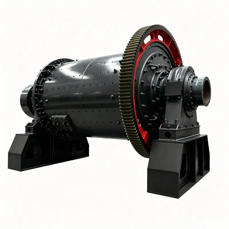
オーバーフローボールミル
オーバーフローボールミルの構造 図9-5は、φ2700mm×3600mmのオーバーフロー……

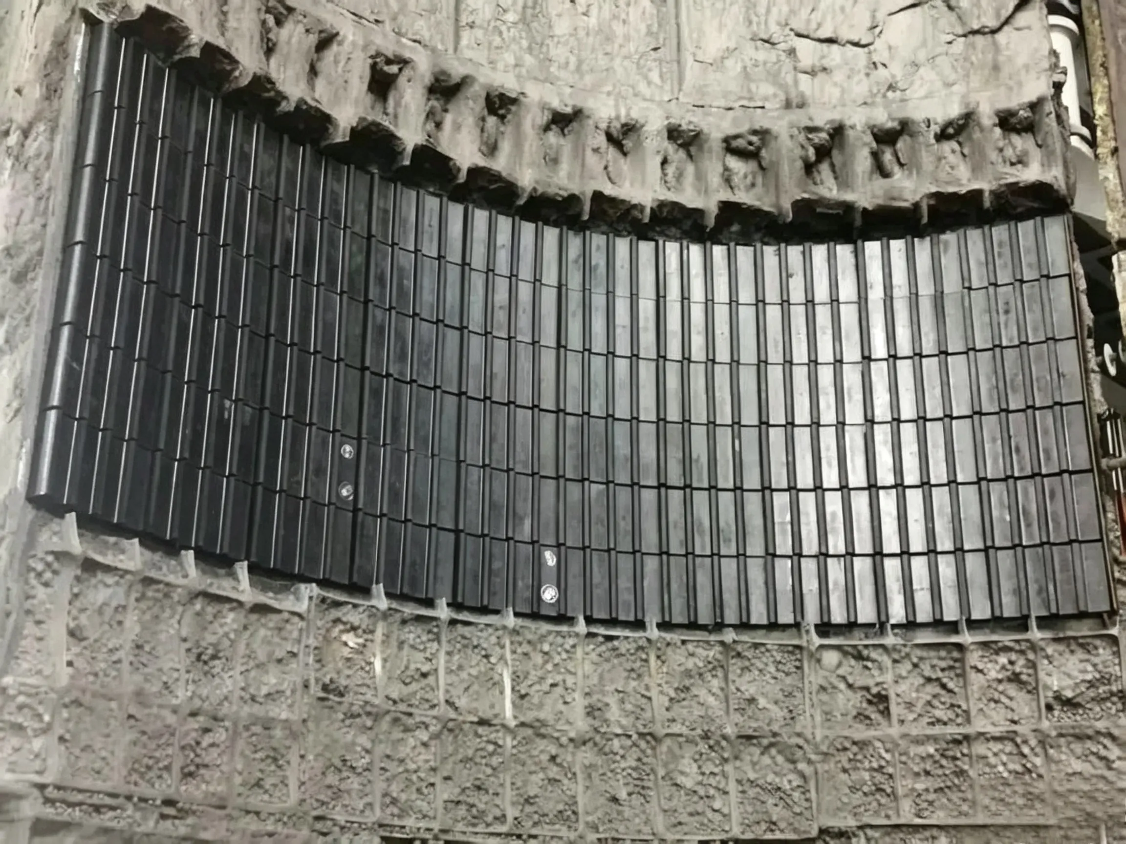
Magnetic Liners
The working principle of magnetic liners is that the liner is made of magnetic material. Through magnetic force, steel objects (especially grinding media – steel balls) and/or magnetic minerals (such as magnetite) are attracted to the liner surface, forming a solid protective layer that becomes part of the liner itself (as shown in Figures 5‑24 and 5‑25).

Permanent magnetic blocks for the metal shell of a rubber‑lined mill

Figure 5‑24 Early magnetic liners

Figure 5‑25 Typical magnetic liner diagram
Figure 5‑26 (referenced but not shown)
In 1975, Andersson first proposed the use of magnetic liners in tumbling mills. Since the liners themselves are magnetic, they can be attached directly to the mill shell by magnetic force without the need for bolted fastening systems (as shown in Figure 5‑26), making installation and replacement easy. Subsequently, in 1982, Weinert proposed an application for a wider range of high‑wear equipment. In the same year, Anon studied and tested magnetic mill liners in tumbling mills, where the grinding energy was transmitted to the ore entirely through the magnetic liners. In such mills, the optimal liner shape should be smooth, but it must have sufficient attractive force to hold ferromagnetic material on the surface to prevent sliding of the mill load against the liner. Since the mid‑1980s, China has begun to place great emphasis on the research, improvement, and promotion of magnetic liners. The core component of a magnetic liner is the permanent magnet, which must have sufficient magnetic energy product and coercive force to generate a strong enough magnetic field on the liner surface and to resist demagnetisation.
Early magnetic liners were made by embedding ceramic magnet blocks in rubber frames. Production practice proved that they were very successful in secondary grinding operations. A typical example of such a liner was the “ore‑bed” magnetic liner developed by Trelleborg (as shown in Figure 5‑24). This liner consisted of magnet blocks encased in rubber boxes, attached to the mill shell, while simultaneously attracting ferromagnetic material to form a protective layer. In 1980, such magnetic liners were installed in a regrind pebble mill at the LKAB Kiruna concentrator in Sweden. Another set was installed at Trellex’s Westbury plant for Blue Circle’s iron‑sand oxide ore. In these cases, the liners used ceramic magnets vulcanised into rubber to protect the mill, but the tensile strength and tear resistance of the rubber were not high enough to resist or absorb the impact of the mill load on the magnets underneath, and the magnets themselves were very brittle. Consequently, such liners were limited to applications where the grinding ball diameter was less than 40 mm (1.5 in) and the mill diameter was less than 3 m (10 ft). For large mills, the grinding media had to be smaller than 25 mm (1 in). Moreover, rubber magnetic liners could only be used on the shell, not on the end liners.
To further protect the magnets in the liners, Miles patented a magnetic liner design in which metal plates were placed around the magnets, thereby preventing direct impact from falling steel balls inside the mill.
Subsequently, in order to prevent the permanent magnets from being damaged by grinding media and material during mill operation, the China Metallurgical Mining Group Corporation developed a magnetic liner with a metal protective box (or metal frame) encasing the magnets, which was termed the metal magnetic liner. Sometimes an elastic layer, such as rubber, was also applied to the surface of the metal frame to provide vibration damping and corrosion protection. The liners were made in block form and could be installed on the mill shell in two ways: one was to attach them directly to the steel shell by magnetic force; the other was to fix them with clamping bars and bolts. During mill operation, due to the magnetic force, the liner surface attracts metallic media (especially broken steel balls, etc.) and magnetic materials, forming a protective layer 30–40 mm thick. This protective layer is self‑renewing and prevents wear and corrosion of the liner. The thickness of the protective layer depends on the magnetic field strength at the liner surface. In 1989, the Anshan Mining Research Institute successfully tested such metal magnetic liners in a 2.7 m diameter × 3.6 m long (9.0 ft × 12.0 ft) regrind ball mill. Subsequently, in 1992, the Jinfa Industrial and Commercial Company of China developed a metal liner and installed it in an iron mine in northern China. It was reported that this magnetic liner showed no significant damage after 9 years of service. Currently, hundreds of sets of metal magnetic liners are in use in Chinese concentrators, with the largest ball mill being 5.5 m diameter × 8.8 m long (18.0 ft × 29.0 ft), using conical grinding media of 35 mm × 45 mm × 40 mm. In 2006, Jinfa installed a set of metal magnetic liners at the Northshore Mining iron ore concentrator of Cleveland‑Cliffs in Silver Bay, Minnesota.
The surface of the metal shell must have a high magnetic flux density. The high‑alloy magnetic steel used for the protective shell requires a hardness of not less than HBW 250, compressive strength not less than 700 MPa, yield strength not less than 400 MPa, reduction of area not less than 45%, and impact toughness greater than 50 J/cm². The shell liner base is a flat surface, while the end liner base is a large flat hemispherical convex body. The geometry, shape, and structure of the metal shell and end liners also have significant effects on the technical performance of the metal magnetic liner. The permanent magnet is the core part of the metal magnetic liner. In addition to attracting the protective layer, the metal magnetic liner must also adhere firmly to the shell and end covers by its own magnetic force. The adhesive layer is made of a special elastic binder, which firmly bonds the magnet blocks inside the metal shell. The adhesive layer has good elasticity, cushioning the slow impact of material and media on the magnets and absorbing impact energy.
The key aspect of the metal magnetic liner is its magnetic field characteristics. The magnetic circuit design adopts an open magnetic system, with the liners arranged alternately in the circumferential direction on the shell and end covers with N‑S poles alternating.
Table 5‑10 compares the main properties of the older rubber magnetic liners and the metal magnetic liners. It can be seen that the harder magnet protective shell allows the metal magnetic liner to be applied in larger ball mills and with coarser grinding media. In this example, the weight of steel balls in the mill with the metal magnetic liner is 2.4 times that of the mill with the rubber magnetic liner.

Figure 5‑26 Example of a boltless magnetic liner
Table 5‑10 Comparison between rubber magnetic liners and metal magnetic liners
| Ball mill parameter | 単位 | Ore‑bed magnetic liner at a copper mine | Metal magnetic liner at an iron mine in the USA |
|---|---|---|---|
| Ball mill size | ft | 10.5 × 16 | 10.5 × 18 |
| Rotation speed | r/min | 17.5 | 18.8 |
| Ball size | うーん | 38 | 51 |
| New feed rate | t/h | 162 | 250 |
| Maximum or design capacity | t/h | 103 | — |
| フィードサイズ | — | 89% –150 μm | 80% –500 μm |
| Product size | % –45 μm | 100 | 50 |
Magnetic liners have the following advantages:
(1) Increased grinding volume. One of the advantages of metal magnetic liners is that they are thinner and lighter than conventional metal liners. Therefore, mills using magnetic liners have a greater effective grinding volume and are also lighter in weight. For example, in the previously mentioned 2.7 m diameter × 3.6 m long (9.0 ft × 12.0 ft) ball mill, the total thickness of the entire magnetic liner, including the protective layer, was only 95 mm (3.75 in), which is significantly less than that of conventional metal liners. This results in a larger grinding working volume, higher throughput, and improved grinding efficiency. In another reported case, a 3.2 m diameter × 4.5 m long (10.5 ft × 14.7 ft) ball mill using metal magnetic liners showed a 7% reduction in operating power consumption, a 5.6% increase in throughput, and a 1% improvement in availability. Similar results were obtained at the Northshore mine with metal magnetic liners.
The magnet blocks, the ball mill shell, and the ore cushion form a small closed magnetic circuit along the circumferential direction of the shell. For large mills, which usually have a manhole, installing magnetic liners can make opening the manhole door laborious and time‑consuming each time. The solution is to use multiple spare manhole doors or to leave the area around the manhole door without magnetic liners. For the magnetic circuit between the non‑magnetic manhole door and the magnetic liners, the magnet blocks near the door frame on both sides form a closed magnetic circuit with the door frame and the shell, so the manhole door is not magnetised, making it easy to install and remove.
(2) Long service life. When magnetic liners are installed, they adhere directly to the metal mill shell by magnetic force without the need for bolts. During mill operation, the magnetic liner attracts broken steel balls and magnetic ore to its surface, forming a protective layer of a certain thickness that prevents the tumbling grinding media and relatively fine material from directly contacting the liner. Because the protective layer is firmly adsorbed onto the magnetic liner surface, it prevents direct contact between the slurry medium and the magnetic liner, greatly reducing mechanical wear and electrochemical corrosion from the slurry and other media, and significantly extending the liner’s service life. Hence, magnetic liners are often referred to as “never‑wear liners.” However, since the ball mill operates continuously, there is still some sliding friction and slight electrochemical corrosion, so magnetic liners do experience minor wear. As the magnetic liner wears and approaches the magnet pole surface, the magnetic field strength at the surface increases, which in turn increases the magnetic attractive force, thickens the protective layer, and enhances protection. Therefore, the initial wear of magnetic liners is relatively fast, but as the metal protective shell wears, the wear rate decreases accordingly. The service life of magnetic liners can reach 10 years or even longer, whereas conventional metal liners typically last less than one year. Thus, the service life of magnetic liners is generally several times to more than ten times that of high‑manganese steel liners, and about 5 times or more that of rubber liners. Although the price of magnetic liners is about twice that of ordinary liners, considering their lower ancillary costs, the payback period is relatively short, generally only a few months.
(3) Lower grinding media consumption. In several industrial applications of magnetic liners, the use of metal magnetic liners has resulted in a reduction of grinding media consumption by about 10%.
(4) Easy maintenance. Metal magnetic liners offer significant advantages over conventional metal liners in terms of maintainability. A single magnetic liner block is lighter and thinner than a conventional alloy steel liner. The mass of a magnetic liner is only about 40% of that of high‑manganese steel, and its thickness is only about 60% as well. Magnetic liners are also easier to install than conventional alloy steel liners; they are attached to the shell by magnetic force without the need for bolts, reducing the labour intensity for workers. Therefore, metal magnetic liners are easy to maintain, quick to replace, and safe to remove and install. Compared with conventional alloy steel liners, the grinding cost per tonne of ore with metal magnetic liners is significantly reduced.
(5) Stable liner performance. Due to the magnetic force of metal magnetic liners, the adsorbed steel balls and magnetic ore form a relatively stable geometric profile that remains almost unchanged over the liner’s service life of several years or more. Therefore, metal magnetic liners provide stable grinding performance. This is quite different from conventional alloy liners, whose geometry changes continuously with wear during the grinding process, causing liner performance to vary with wear. Consequently, operational adjustments must be made to compensate for the wear of alloy steel liners. In practice, to maximise performance over the life of an alloy steel liner, the angle of new liners is often set too steep, but at the end of life the lifter bars become too low, reducing lifting capacity and grinding efficiency. At the same time, the geometric shape formed by the magnetically attracted material can effectively lift the material and promote efficient cascade grinding.
(6) High grinding energy efficiency. It is frequently reported that metal magnetic liners improve grinding efficiency. Possible reasons are as follows: 1) The geometry of the protective layer formed by magnetic attraction affects the mill load (including grinding media and ore); magnetic liners tend to cause the mill load to be more compact than conventional metal liners. 2) There may also be a residual magnetic effect that brings ore particles and grinding media closer together. Both of these factors lead to more effective attrition‑type comminution of ore particles between grinding media (steel balls), making inter‑particle comminution the dominant breakage mechanism. 3) The wave‑like profile formed by the attraction of steel balls and magnetic minerals contributes to improved grinding efficiency.
Magnetic liners are widely used for various strongly, moderately, and weakly magnetic minerals. Magnetic minerals include: strongly magnetic minerals such as magnetite and maghemite; moderately magnetic minerals such as ilmenite and martite; and weakly magnetic minerals such as most iron‑manganese ores and hematite. They can also be used for non‑magnetic minerals such as copper, gold, lead, and zinc. Notably, during the initial period of magnetic liner use, a certain amount of ferromagnetic material—such as broken steel balls and scrap iron—needs to be added periodically to help form the protective layer.
デメリット: Although magnetic liners provide good economic benefits in application, they also have some shortcomings. The magnetic field strength at the feed end is weaker, resulting in a relatively thinner protective layer, and direct impact from grinding balls can cause demagnetisation, so the liner life at the feed end is not as long as that of the shell liners. Mid‑life shutdowns for replacement are necessary, which causes inconvenience to production and affects equipment efficiency. Installation requires a relatively high surface flatness of the shell wall and end covers; uneven surfaces are not permitted. The magnetic orientation of the magnetic liners on the discharge and feed end covers must be perpendicular to the direction of the centrifugal force they experience. Magnetic liners (including metal magnetic liners) are still limited to small or medium‑sized mills due to their poor impact resistance. In addition, magnetic liners generally cannot be used in ball mills where the ball diameter exceeds 80 mm, because larger balls generate greater impact forces, and the poor impact resistance of magnetic liners can lead to relatively rapid demagnetisation.
 English English
 Spanish
 Russian
 Arabic
 Swahili
 French
 Turkish
 Portuguese
 Korean
 Japanese
 German
 Italian