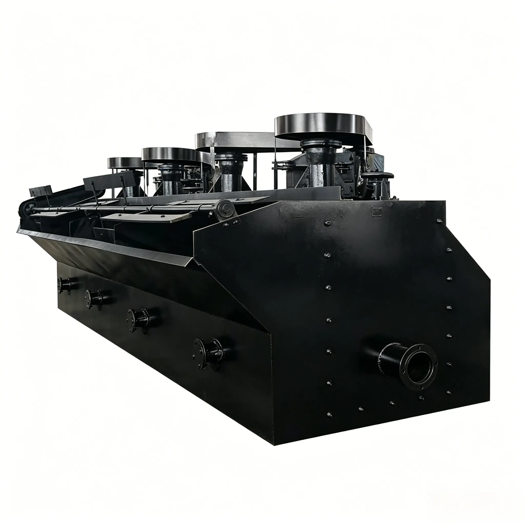
XJZ浮選機
XJZ型浮選機 には、何千台もの旧式のXJ型浮選機が……

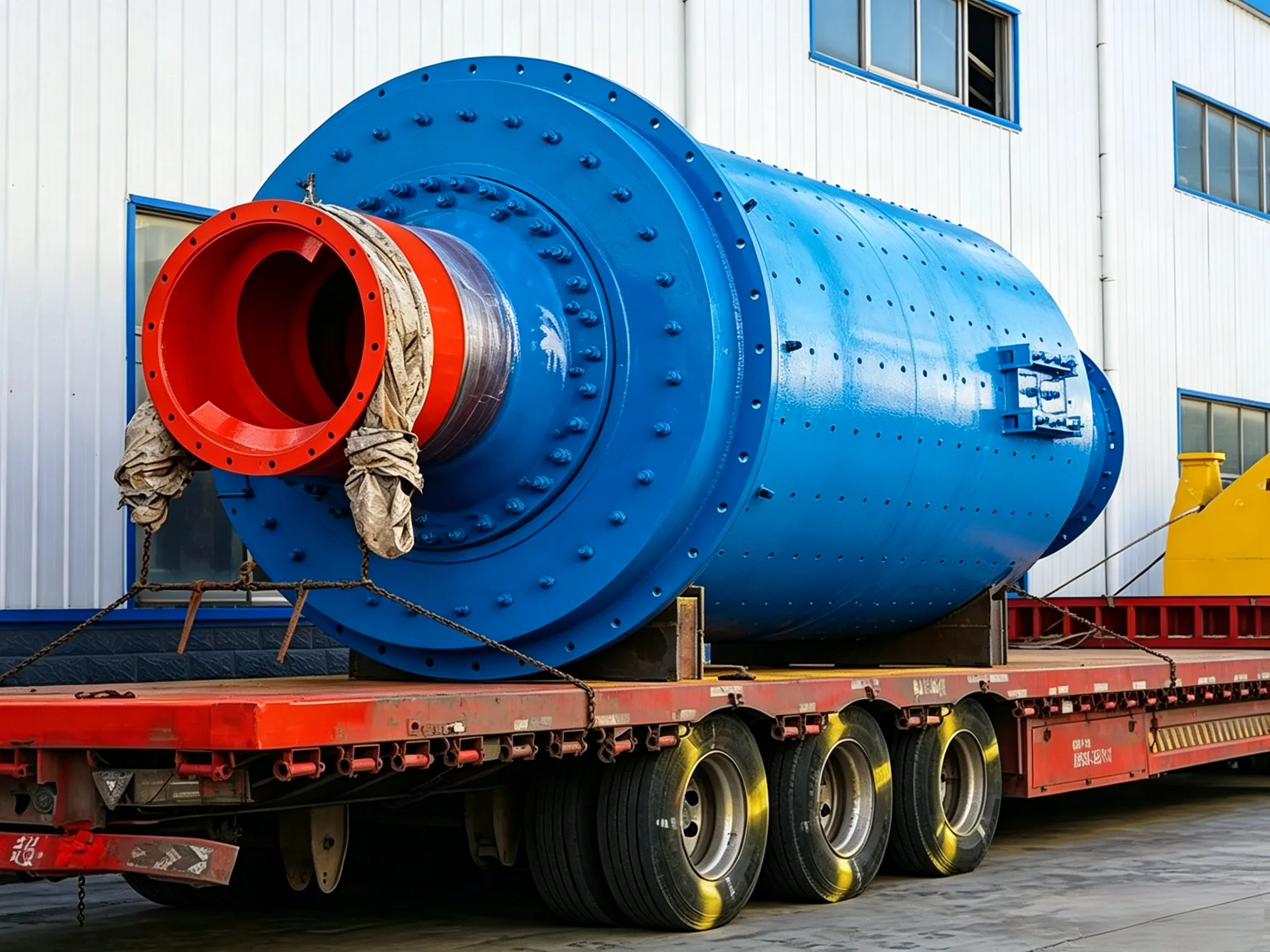
It is frequently observed that the connecting bolts between the mill’s hollow shaft and the shell break frequently during normal operation. Some fractures occur at the root of the bolt head, some near the nut, and others at the junction between the shank and the thread. The fracture surfaces are relatively flat. Each time a broken bolt is replaced, it is retightened, but it breaks again shortly afterward.
There are many factors that cause bolt fracture in mills, summarized as follows:
① Bolt material does not meet design requirements, and bolt structural design is improper
a. Bolt material issues are one of the main causes of connecting bolt fracture failures in newly commissioned mills. Improper material selection, unsuitable heat treatment processes for the bolt shank, careless quenching operations, and improper tempering time control can easily lead to microcracks at the root of the bolt head. Microcracks can also occur when the final forging temperature is too low during the forging of the bolt head.
b. In the structural design of the bolt head, a machined fillet is provided at the root of the bolt head. This fillet is often neglected during turning operations. The corresponding position of the screw hole in the shell flange, which mates with this fillet, is not designed with the necessary chamfer. As a result, during assembly, it is difficult for the bolt head plane to fit tightly against the shell plane. Local stress concentration cannot be eliminated, leading to bolt fracture.
② Poor assembly quality
a. The perpendicularity of the flange plane seriously exceeds the tolerance, or the shell is not manufactured according to the correct fabrication procedure, resulting in a large assembly clearance. This reduces the rigidity of the bolted connection, causing fatigue cracks in the bolts and eventually leading to fracture.
b. Since tightening of the bolts is generally performed based on the worker’s experience, it is difficult to ensure uniform stress distribution among all bolts, which can also cause bolt fracture during mill operation.
③ Attenuation of nut clamping force and loss of nut self-locking ability
a. Excessive thread fit clearance or too large a thread pitch results in poor self-locking performance.
b. Poor thread surface roughness leads to extrusion between the thread flanks under load, increasing the pitch diameter fit clearance and causing the nut to back off.
c. The inner surface of the mill shell end cover is an unmachined surface. During mill operation, under load, the high points on the contact plane between the bolt head and the shell end cover are pressed flat (or pressed down). Consequently, some individual tightened nuts become relatively loose, causing uneven stress distribution among all bolts. With each revolution of the mill, one or several bolts are subjected to an impact. The end cover steel plate beneath the bolt head is indented by the impact, and the bolt head becomes deformed. The looser the bolt, the greater the impact force, and the larger the indentation and deformation become.
d. The connecting bolts between the hollow shaft and the shell end cover have right‑hand threads, and the rotation of the mill causes the nuts to loosen.
e. During the trial operation of the mill, bolt loosening generally goes unchecked, and no tightening measures are taken. After entering formal production, the loosening becomes increasingly severe, and the flange clearance gradually increases. A thin layer of material becomes sandwiched between the two flange planes, reducing the rigidity of the connection pair and increasing the bolt stress amplitude. Additionally, due to the blocking effect of the flange spigot, this material layer is difficult to remove, thereby accelerating bolt fatigue failure.
f. During operation, the impact of grinding media and material on the shell causes vibration of the rotating parts of the mill, leading to nut loosening. The degree of nut loosening caused by attenuation of clamping force is not uniform. Bolts that have not loosened are consequently subjected to increased loads, and if not detected in time, they will break.
④ Excessively loose fit between the fitted bolts and the reamed holes causes relative radial slippage between the hollow shaft and the shell end cover. In this case, the bolts (especially if some nuts are loose, making the situation worse) are subjected not only to axial tensile impact forces but also to radial shear impact forces. The unfavorable loading conditions cause the bolts to fracture at the junction between the bolt head and the shank, at the shank itself, or at the minor diameter of the thread.
⑤ Poor rigidity of the shell end cover material, or non‑parallelism between the inner surface of the shell end cover and the outer surface of the large hollow shaft flange, can also lead to bolt fracture.
⑥ High operating temperature of the mill reduces the mechanical properties of the shell flange connecting bolts. In some cases, it even causes deformation of the thread profile, reducing connection strength and resulting in fracture.
⑦ Improper maintenance methods can also cause bolt fracture. For example, if there is no regular inspection system or if the system exists only in name, loose bolts cannot be detected and retightened in time. In another case, broken bolts are not replaced promptly, and the mill is started with missing bolts, causing adjacent bolts to also break. Furthermore, if the replacement bolts are made of a different material from the original design bolts, the bolts will experience uneven stress, leading to fracture of the weaker ones.
After a fault occurs, especially when bolts break frequently, it is necessary to identify the cause and take corresponding measures.
① Improve the quality of the bolts themselves.
a. The connecting bolts should preferably be made of No. 45 medium carbon steel or 40Cr quenched and tempered steel. A3 steel, low‑carbon steel, or other lower‑strength materials should not be used for bolts.
b. When machining bolts and nuts, the thread surface roughness should at least reach Ra 1.6. Suitable fine‑pitch threads should be selected, and attention should be paid to thread run‑outs. Match the bolts and nuts so that the clearance between the pitch diameter and the major/minor diameter is close to zero, improving the fit between the nut and bolt, reducing stress concentration, and ensuring thread engagement and connection strength.
c. If self‑made bolts and nuts cannot be heat‑treated in a dedicated facility, the laboratory high‑temperature electric furnace can be used for quenching and tempering. Heat the workpiece to 850 °C in the furnace, hold for 40 minutes, quench in oil, then hold at 500 °C for 2 hours and remove for air cooling. To disperse working pressure, place a steel plate under the workpiece.
② Establish a system of regular and irregular inspections to identify and resolve problems promptly.
a. Replace broken bolts in a timely manner (if only a small number, e.g., 1–2 bolts are broken, replacement can be scheduled during planned maintenance to reduce downtime).
b. Tighten loose bolts promptly.
c. For deformed bolt holes, such as local ovality, burrs, or raised edges, carefully file them smooth during repair to prevent residual clearance after assembly.
d. If a gap appears at the spigot after assembling the hollow shaft onto the shell flange, an additional annular steel plate approximately 10 mm thick and 80–100 mm wide can be welded at the spigot. The inner diameter should be machined to match the spigot size, and the plate should be divided into 3–4 segments along the circumference. Drill several 20 mm diameter holes in the plate and weld it to the shell flange using the stud welding method to increase strength and prevent spigot failure.
e. If a double‑nut locking design is adopted, ordinary nuts of the same material and size can be used. If two nuts of different thicknesses must be used, the thin nut should be installed first, followed by the thick nut.
f. If the flange planes are severely roughened or burred, use an angle grinder or manual sander to grind them, and finally hand‑finish with abrasive blocks to make them flat.
③ The bolts at the two ends of the mill’s hollow shaft should use left‑hand and right‑hand threads respectively, to suit left‑side and right‑side drives. The configuration of left‑hand and right‑hand threaded bolts can be determined as follows: Stand at one end of the mill and look along the hollow shaft axis to see its direction of rotation. If it rotates counterclockwise, this end of the hollow shaft should use right‑hand threaded bolts, and the other end should use left‑hand threaded bolts. If it rotates clockwise, this end should use left‑hand threaded bolts, and the other end should use right‑hand threaded bolts.
④ During mill operation, regularly check whether the nuts on the hollow shaft and shell end cover are loose. During the trial operation period, check every 1–2 hours. Retighten the nuts with the initial torque. If loosening is found, tighten immediately and replace the locking wire. If there is no loosening for three consecutive checks (i.e., retightening holds as initial), check every 24 hours. If there is no loosening for three consecutive shifts (i.e., 24 hours), check once every 24 hours. If there is no loosening for three consecutive working days (i.e., 72 hours), check once a week. Thereafter, revert to normal routine and check once a week.
⑤ For broken bolts, in order to prevent new fractures (i.e., recurrence of frequent bolt breakage) after replacement, it is advisable to completely replace all connecting bolts on that end. The fault treatment procedure is as follows:
a. Make all necessary preparations, including preparing repair tools and equipment, arranging personnel, and stocking sufficient hollow‑shaft connecting bolts and rough‑machined fitted bolts (to be finish‑turned after match reaming).
b. In the compartment where the broken bolt is located, remove the grinding media, dismantle the mill discharge grate plate, the lifter plate, or the mill head liner. Loosen the main bearing cap bolts and use jacks to lift the mill body clear.
c. Loosen the hollow‑shaft connecting bolts, remove the hollow shaft, and place it on the ground.
d. Clean the contact surfaces between the hollow shaft and the end cover, removing any material interlayer and other debris, until they are completely dust‑free, achieving “good fit and absolutely no clearance.”
e. Align and install the bolts, tightening them symmetrically. After match reaming the eight fitted bolts, install them securely. Then reassemble the mill discharge grate plate, lifter plate, or mill head liner, add grinding media, and prepare for operation.
f. After 24 hours of test operation following maintenance, retighten the connecting bolts.

 English English
 Spanish
 Russian
 Arabic
 Swahili
 French
 Turkish
 Portuguese
 Korean
 Japanese
 German
 Italian