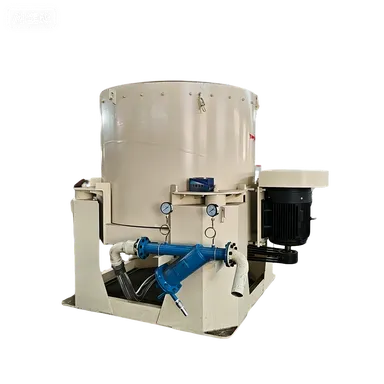
遠心濃縮機
遠心濃縮機 – 高効率微粒子重力濃縮機 製品概要 遠心濃縮機…

① Separation of grinding media. It keeps the average size of grinding media in each compartment gradually decreasing from the coarse-grinding compartment to the fine-grinding compartment, so that large media are used for large particles and small media for small particles, thus effectively utilising the grinding capability of the media.
② Sizing of the material being ground. The slots on the diaphragm retain larger particles in the preceding compartment, allowing them to be reduced to a size suitable for the next compartment before they enter it.
③ Control of the flow velocity of material and gas through the mill. Proper selection of the slot width, length, total open area, the lowest position of the slots, and their arrangement has a favourable effect on the material filling degree, the flow velocity of material and gas in each compartment, and the maintenance of an appropriate ball‑to‑material ratio within the compartments.
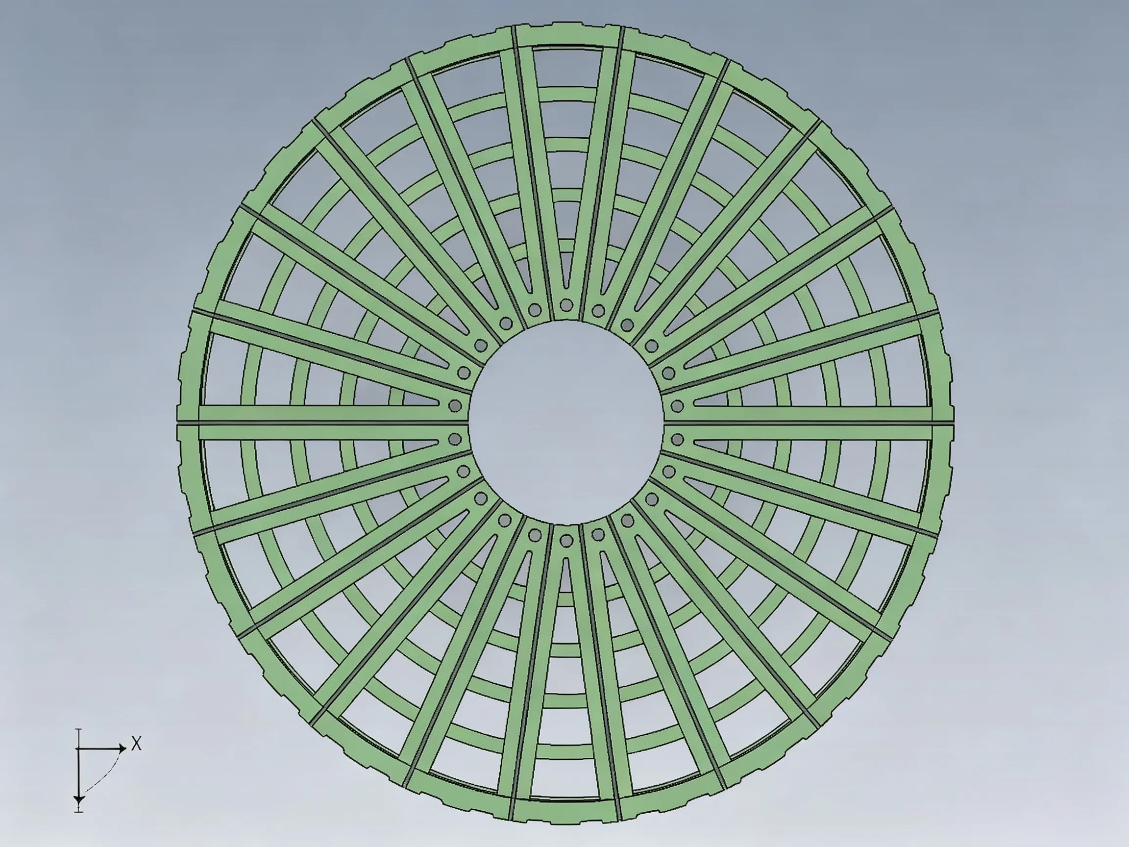
① Single‑layer diaphragm. It consists of several sector‑shaped grate plates. The outer ends are bolted to the mill shell, while the inner ends are connected together by a central circular plate. The holes in the central plate serve for ventilation and to prevent grinding media from migrating between compartments. Material that has been ground to a size smaller than the grate openings is pushed by the fresh feed through the slots of the diaphragm into the next compartment. Before passing through the single‑layer diaphragm, the material flow velocity in the compartment is relatively low and is also influenced by the material level in the subsequent compartment. The single‑layer diaphragm has a simple structure, occupies little effective mill volume, and is not easily damaged, so it is widely adopted. For two‑compartment mills with relatively small production capacity and limited volume, where the product fineness tends to be coarse, the single‑layer diaphragm is particularly advantageous.
② Double‑layer diaphragm. It consists of a front plate (also called a sieve plate) and a rear plate (also called a blind plate). The front plate allows material to pass through, while the rear plate protects the lifting plates from being damaged by the grinding media in the next compartment. Between the two plates, lifting scoops (or vanes) are installed. After material passes through the slots of the front plate into the double‑layer diaphragm, it is lifted by the scoops as the mill rotates, then falls onto the material‑guide cone and slides into the adjacent compartment. The double‑layer diaphragm is typically used in larger three‑ or four‑compartment tube mills, and is often installed between the first and second compartments. It allows the material in the front compartment to move forward more quickly and is not affected by the material level in the adjacent rear compartment. Double‑layer diaphragms can be further divided into two types: the classifying diaphragm and the lifting diaphragm. The classifying diaphragm can perform a rough separation of the material, returning coarse particles to the first compartment and allowing fine particles to enter the second compartment. The lifting diaphragm only accelerates the material flow through the mill and is commonly used in wet‑process mills. The double‑layer diaphragm has a complex structure, reduces the effective mill volume after installation, and is more prone to damage, so it is less frequently used.
 English English
 Spanish
 Russian
 Arabic
 Swahili
 French
 Turkish
 Portuguese
 Korean
 Japanese
 German
 Italian