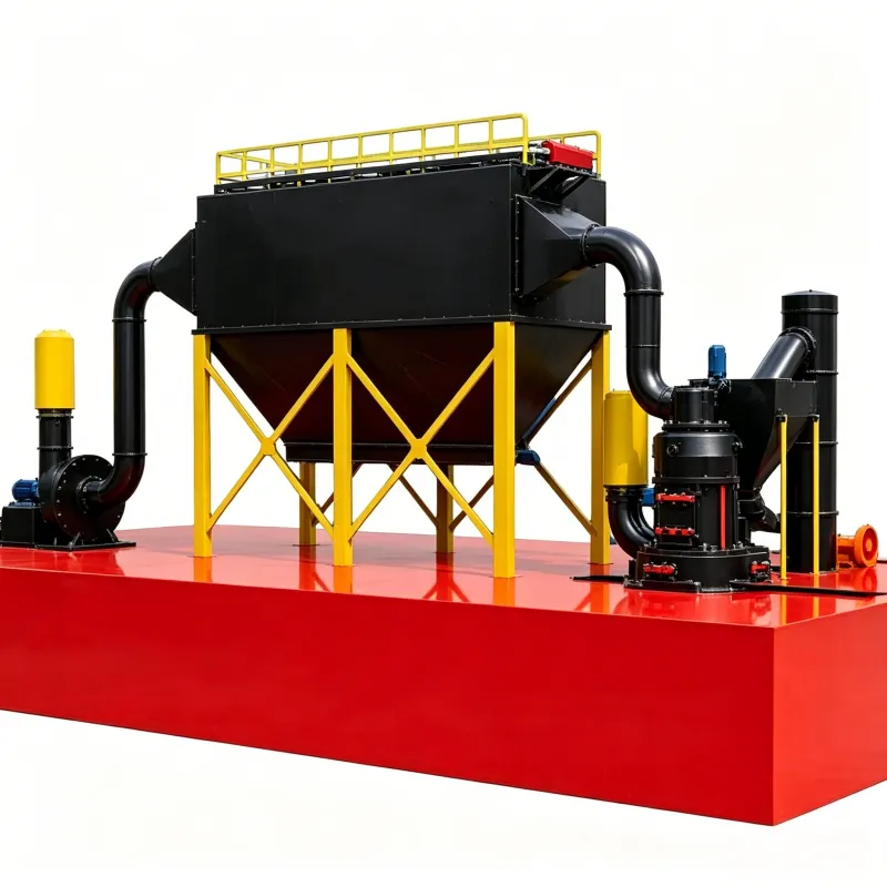
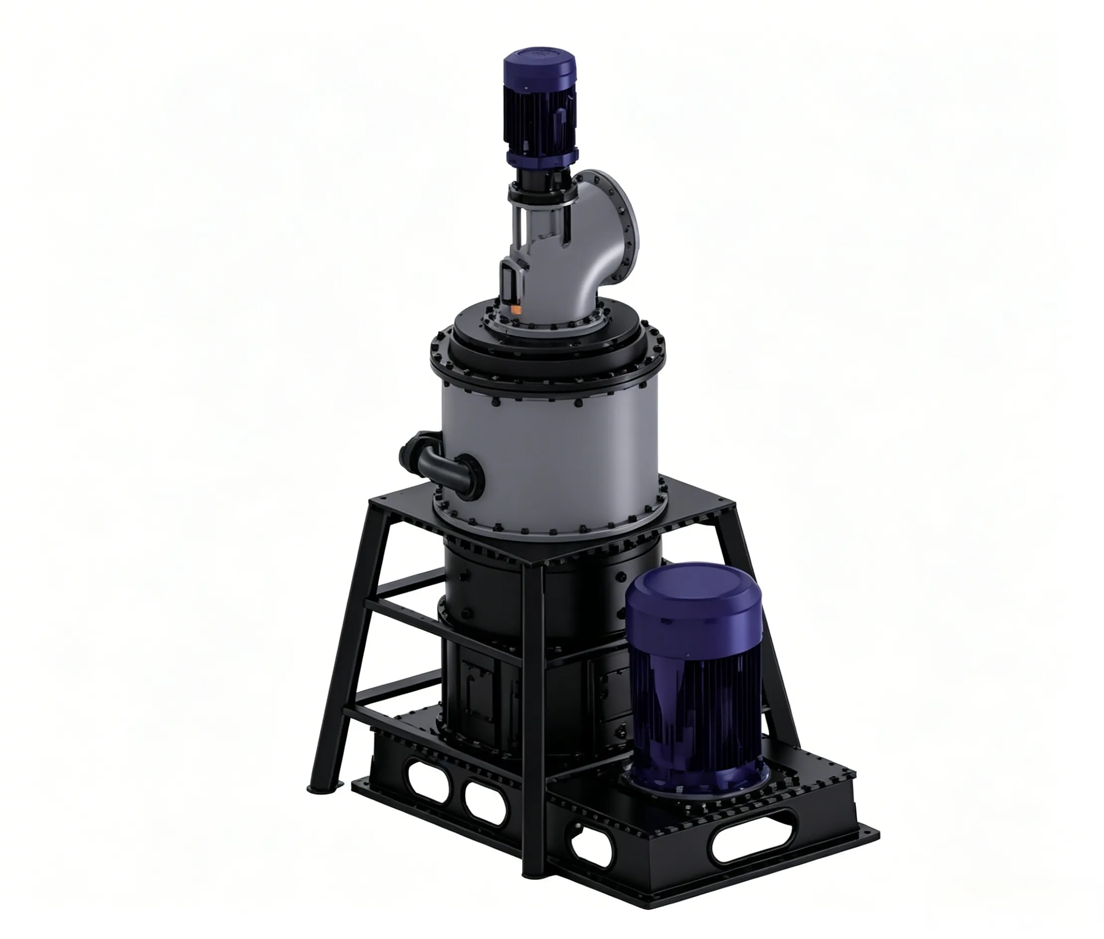
開放回路式レイモンドミル
オープン回路式レイモンドミルの概要 KXオープン回路式レイモンドミルは…


The structure of a full/semi-autogenous grinding mill (AG/SAG mill) is mainly composed of a feed chute, shell, discharge system, bearing and lubrication system, and drive and control system. The mill shell section is further subdivided into the feed end, cylindrical shell, grate plates, pulp lifters, and discharge end. The drive and control system includes the main motor, coupling, dynamic clutch, slow-speed drive device, electrical controls, etc. The bearing and lubrication system also includes jacking devices, among others. Figure 3-1 shows the structural diagram of a mechanically driven AG/SAG mill.

Figure 3-1 – Structural diagram of the mechanically driven AG/SAG mill
For large and medium-sized AG/SAG mills, the feed end generally adopts a trolley-type chute structure (as shown in Figure 3-2), with wear-resistant liners embedded inside. Due to the large feed size of AG/SAG mills, the feed chute must have a considerable slope and height to ensure smooth feeding. If cyclone underflow is returned, a Rock Box may need to be added to reduce its impact. For large mills, the chute of the feed trolley passes directly through the hollow shaft at the feed end into the mill interior, so the hollow shaft does not experience wear and does not require liners. For small and medium-sized mills or AG/SAG mills, the hollow shaft still needs liners, and the material must pass through a section of the hollow shaft before entering the mill interior.

Figure 3-2 – 3D structure of the feed trolley for the AG/SAG mill
Feed-End Hollow Shaft
During mill startup and shutdown, the hollow shaft (as shown in Figure 3-3) requires high-pressure lubricating oil to lift the journal and form an oil film, thereby preventing dry friction on the sliding surfaces. During normal operation, low-pressure oil is supplied, and the rotational motion of the journal generates a hydrodynamic oil film. At the hollow shaft bearing, a thrust bearing is usually provided to limit axial movement of the mill. For large mills, a load cell is also installed at the hollow shaft bearing to measure and monitor the weight of the material inside the mill, which is a critical parameter for mill safety and automatic control. Serpentine cooling water pipes are embedded in the bearing liner; cooling water can be introduced when necessary to reduce the bearing pad temperature.
Each main bearing is equipped with a temperature sensor for dynamic monitoring of the bearing pad temperature. When the temperature exceeds a preset value, an automatic alarm is triggered and the mill is shut down. Annular seals are provided at both ends of the main bearings, and grease is filled through the lubricating oil pipes to prevent oil leakage and dust ingress.

Shell
The shell of the AG/SAG mill consists of the feed end head, cylindrical shell, discharge end head, and discharge bell-mouth. It can be of either integral or split construction, and the hollow shaft is usually cast. Small mills typically adopt the integral type, while as the mill size increases, the number of component parts increases. Critical parts are subjected to ultrasonic testing after rough machining, and magnetic particle inspection of the surfaces after finishing. The journal surface of the hollow shaft is polished after machining. All connections between the end heads and the shell are made with high-strength bolts. High machining accuracy is required to ensure reliable connections and the concentricity of the two journals after final assembly. When the split type is adopted, flange connections with spigot positioning are used. The inner wall of the mill shell is lined with rubber liners, as shown in Figure 3-4.
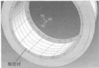
Figure 3-4 – Shell of the AG/SAG mill
Liners
All areas inside the mill that come into direct contact with ore or pulp are equipped with liners (as shown in Figure 3-5). They are the renewable wear surfaces of the mill and constitute one of the major components of production costs (accounting for about one‑third of the operating cost of an AG/SAG mill). The main functions of the liners are as follows:
(1) To protect the mill shell from damage caused by severe impact, abrasion, and/or chemical corrosion from the material inside the mill, and to provide a replaceable wear‑resistant surface.
(2) To transfer the energy of the rotating mill shell to the grinding media and ore inside the mill, causing them to move and thereby achieve the grinding function.
The wear rate of the liners is one of the key performance parameters. The liner thickness must be continuously monitored to avoid wear of the mill shell. In addition, liner performance has a significant impact on mill throughput, equipment availability, liner life, energy efficiency, and production costs. If the liner wear rate is too high, it will greatly increase liner material costs and lead to unscheduled shutdowns for liner replacement, reducing equipment availability and average throughput. For semi‑autogenous mills that use steel balls as grinding media, incorrect liner design may cause the steel balls to directly impact the liners, resulting in liner breakage and/or ball fracture, which substantially increases production costs and maintenance downtime.

Figure 3-5 – Liners of the AG/SAG mill
(a) Liner assembly drawing; (b) Feed-end liners; (c) Shell liners; (d) Grate plates; (e) Pulp lifters
3.1.4.1 Shell Liners
The shell liners are the interface that transfers energy to the material inside the mill, and they play a decisive role in the grinding efficiency of the material. The geometry of the shell liners controls the motion of the material inside the mill, which in turn leads to different grinding mechanisms, grinding efficiencies, and product size characteristics. In industrial practice, not only the geometry of the new liners but also the changes in geometry and their effects throughout the wear process must be considered. Therefore, the design of the shell liners (including the lifters on them) is crucial for increasing the throughput per unit time of the mill. It is worth noting that the geometry of the shell liners varies with the properties of the ore, the required grinding fineness, and other factors.
3.1.4.2 Grate Plates
In principle and function, grate plates are similar to classification equipment such as screens, allowing material smaller than the grate openings to pass through. The driving force for material passage through the grate plates is the pressure difference across the plates. The main functions of the grate plates include:
(1) Retaining coarse material (and grinding media in the case of SAG mills) inside the AG/SAG mill. For AG mills, the coarse ore itself acts as grinding media. At the same time, if the ore pieces are too large, they may exceed the maximum feed size allowed by the pebble crusher, making it impossible to process them effectively or affecting the overall crushing performance. For SAG mills, the grate plates limit the loss of grinding media by preventing steel balls from being discharged.
(2) The grate plates also serve to limit the discharge of material (including medium and small ore pieces). For AG/SAG mills that require fine grinding, this helps maintain a high mill charge level, enhances the attrition grinding mechanism, and thus leads to finer grinding.
However, if the resistance of the grate plates to the slurry flow is too high, the slurry will accumulate inside the mill up to a critical level. Up to this critical level, it helps improve the grinding efficiency of fines, especially in AG grinding where it can increase the fineness of the product. But excessive accumulation creates a slurry pool inside the AG/SAG mill, which reduces grinding efficiency. This is because the grinding media must first pass through the slurry layer before impacting the ore, losing kinetic energy. Sometimes, even if there is no slurry layer above the ore, a thick slurry coating on the ore surface similarly reduces the impact comminution force of the grinding media.
If a slurry pool exists inside the mill, large mills often use grate plates with curved lifters to increase their throughput capacity. Sometimes, in order to make full use of pebble crushing, the grate plates are designed with large open areas to increase the speed at which pebbles pass through the grates.
The key design parameters for grate plates include the open area, the size and shape of the openings, the position of the openings, and the height of the lifters on the grates. If the downstream pulp lifters have sufficient capacity, an expected slurry discharge rate can be achieved by optimising the grate plates.
Pulp Lifters
The pulp lifters act like a pump to discharge the slurry that has passed through the grate plates. Radial pulp lifter bars resemble the spokes of a wheel, but they have a wear‑resistant bottom plate that protects the discharge end cone of the mill (acting as a liner). When the mill rotates, the slurry in each pulp lifter compartment is lifted; when the compartment passes beyond the horizontal position, the slurry flows toward the central discharge opening and is eventually discharged from the mill through the bell‑mouth.
To accelerate and improve the efficiency of slurry discharge, the pulp lifters can be made in a curved configuration. However, the mill is limited to unidirectional rotation, which may affect the service life of other liners in large mills and increase liner costs.
There are two key parameters for evaluating the performance of pulp lifters: backflow and carry‑over. Backflow refers to the slurry in the pulp lifter compartments flowing back through the grate plates into the grinding chamber of the mill. This can exacerbate the formation of a slurry pool in the grinding chamber and accelerate the wear of the grate plate openings. Carry‑over means that during one revolution of the mill, the slurry in the pulp lifter compartments cannot be completely emptied. When the pulp lifter compartment turns downward from the horizontal position, remaining slurry inside no longer moves toward the central discharge opening but begins to move toward the periphery of the mill. Since slurry moves faster than coarse ore, what is left behind is mainly pebbles. However, when moving toward the periphery, the slurry typically impacts the bottom of the pulp lifter compartment, causing accelerated wear.
For the pulp lifters, the number of compartments must be considered. If the number is too few, each compartment is large, which increases backflow and requires more time to empty each compartment, making carry‑over more likely. If the number is too many, the walls of the compartments take up too much space, reducing the overall capacity of the pulp lifters, and each compartment becomes smaller, increasing the chance of large ore pieces or steel balls getting jammed, which further reduces discharge capacity.
Discharge End
The hollow shaft at the discharge end of conventional AG/SAG mills is almost the same as that at the feed end, but without thrust bearings and load cells. Figure 3‑6 shows a view from the discharge end looking towards the mill. In some regions, especially in Africa (South Africa), there are special discharge end designs, as shown in Figure 3‑7. The discharge end of the mill has only grates similar to grate plates. Once the material passes through, it is discharged directly, without the need for pulp lifters, so the discharge of material is unrestricted.
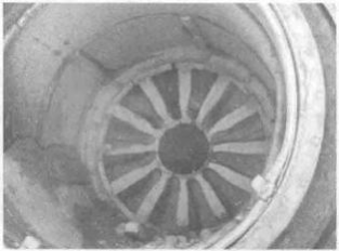
Figure 3-6 – Discharge end of a conventional AG/SAG mill

Figure 3‑7 – Discharge end without a hollow shaft (usually also without pulp lifters)
Trommel Screen
To simplify the grinding circuit, small and medium-sized mills are usually equipped with a trommel screen at the discharge end (as shown in Figure 3‑8), which is used for classifying the mill discharge, thereby eliminating the need for an external vibrating screen. It is almost the same as the discharge trommel screen of a ball mill, but the screen apertures need to be changed according to the process requirements. In addition, the trommel screen of an AG/SAG mill does not have a reverse spiral inside. For large mills, the classifying capacity of the trommel screen is limited or generally far from sufficient to achieve effective classification; therefore, most large mills are not equipped with a trommel screen.
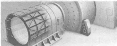
Figure 3-8 – Trommel screen at the discharge end of the AG/SAG mill
Lubrication System
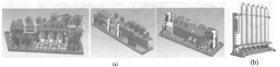
The high-pressure part of the lubrication system provides high-pressure oil for lifting the hollow shaft, while the low-pressure part supplies lubrication and cooling to the mill hollow-shaft bearings and thrust bearings. The accumulator contains high-pressure nitrogen gas. In the event that the lubrication system fails and the mill trips and shuts down, the mill does not come to an immediate complete stop; at this time, the high-pressure nitrogen forces lubricating oil for a short period to the areas that must still be lubricated, thereby preventing mill damage. Its 3D view is shown in Figure 3‑9.
Drive System
With the increasing scale of AG/SAG mills, two notable changes and requirements have emerged for the mills supplied by the machinery and electrical industry:
(1) As the mill diameter increases, the individual motor power also increases.
(2) The demand for variable‑speed motors increases. This is because it is necessary to improve the adaptability of the grinding operation to variations in ore properties, which can effectively increase throughput or adjust the grinding fineness in a timely manner to improve recovery.
The drive system for an AG/SAG mill is usually designed with the following key factors in mind:
(1) Starting current or load.
(2) Maximum power limit.
(3) Whether variable speed is required.
(4) Maintenance workload and difficulty.
(6) Production operation and maintenance costs.
The drive configurations for AG and SAG mills are first divided into geared drives and gearless drives. Geared drives are further divided into synchronous motor drives and asynchronous (induction) motor drives. Depending on the power level, synchronous and asynchronous motor drives can be single‑drive or dual‑drive. Therefore, the commonly used drive configurations include five types: synchronous motor single drive, asynchronous motor single drive, synchronous motor dual drive, asynchronous motor dual drive, and gearless ring motor drive. The commonly used mill drive systems are shown in Figure 3‑10.

Figure 3‑10 – Commonly used mill drive systems (12)
Geared drive transmits power to the mill through a pinion and ring gear arrangement. For single‑drive mills, according to the layout, they are divided into left‑hand and right‑hand configurations (when viewed from the feed end looking in the direction of material flow, if the main motor is on the left side of the shell it is left‑hand, and if on the right side it is right‑hand). Depending on the process layout requirements, the drive unit can be placed at either the feed end or the discharge end. For geared drives, soft‑start methods are typically adopted to reduce starting torque and current, enabling staged startup of the main motor and the mill shell, lowering the installed power, and reducing the starting current by several times compared with direct starting. Commonly used soft‑start methods include air clutches and liquid resistance starters; with the development of the electronics industry, variable speed drives (VSDs) are also occasionally used.
Gearless drive is a special motor arrangement. The entire mill acts like a motor, with the mill shell serving as the rotor and the ring motor as the stator, similar to a conventional motor. It inherently has variable‑speed capability.
Due to mechanical strength limitations, the maximum power of a geared single drive is 8.5–11.5 MW, while a geared dual drive can reach up to 15–17 MW. For gearless ring motors, they are typically used for powers >10 MW, and the current maximum power of a gearless ring motor is 28 MW.
Electric Motor
3.2.1.1 Asynchronous (Induction) Motor
The basic structure of a three‑phase asynchronous motor is shown in Figure 3‑11. It mainly consists of two fundamental parts: the stator and the rotor.
(1) Stator. The stator is the stationary part of the motor, used to generate a rotating magnetic field. The stator core is built from laminated silicon steel sheets, with many slots on the inner circumference to accommodate the stator windings. It is mainly composed of the stator core, stator windings, and the frame.
(2) Rotor. The rotor is the rotating part of the motor, composed of the rotor core, rotor windings, and the shaft. The rotor core is also made of laminated silicon steel sheets, with many slots on the outer circumference to hold the rotor windings. Its function is to obtain rotational torque under the action of the rotating magnetic field. Depending on the rotor construction, rotors are classified as squirrel‑cage rotors and wound‑rotor (slip‑ring) rotors, the difference lying in the rotor itself.
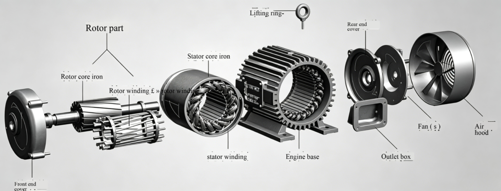
Figure 3‑11 – Structure of an asynchronous motor
The advantages of asynchronous motors lie in their simple structure, stable performance, easy maintenance, low cost, and the simplest manufacturing process, which is why they are the most widely used motors in industry.
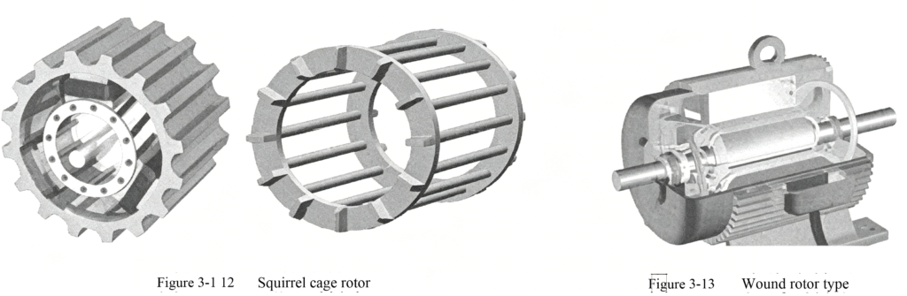
A squirrel‑cage three‑phase asynchronous motor (as shown in Figure 3‑12) refers to a motor whose stator has three‑phase distributed windings and whose rotor is a cage‑type conductor bar. Because the conductor bars resemble a squirrel cage, it is called a squirrel‑cage asynchronous motor. The rotor of a squirrel‑cage motor is made of metal bars, either copper or aluminum. Aluminum is relatively cheap and is widely used in less demanding applications, but copper has better mechanical and electrical conductivity than aluminum, so the vast majority of rotors are made of copper. When three‑phase AC power is applied to the stator windings, a rotating magnetic field is generated. The closed conductor bars in the rotor induce electromotive force and current as they cut the magnetic field lines of the stator. The current‑carrying conductors in the magnetic field are subjected to Lorentz forces, which drive the rotor to rotate. Once the manufacturing process solved the problem of broken bars, the reliability of squirrel‑cage motors far exceeded that of wound‑rotor motors. Their disadvantage is that the torque obtained by the metal rotor cutting the magnetic lines in the rotating stator field is relatively small, and the starting current is large, so they are generally not suitable for loads requiring high starting torque. Although increasing the core length can provide more torque, the improvement is very limited. Wound‑rotor motors, on the other hand, energise the rotor windings through slip rings during starting, creating a rotor magnetic field that moves relative to the rotating stator field, thus obtaining greater torque. In addition, a liquid resistance starter is connected in series to reduce the starting current, and its resistance is controlled by an electronic control device to vary with the starting process. Since squirrel‑cage motors have a simple structure, low cost, and relatively simple control, they are widely adopted.
liquid resistance starter uses a specially formulated aqueous solution as the resistor, with electrode plates introduced into a specially designed high‑voltage resistance tank and connected into the stator circuit of the motor. During starting, by controlling the liquid resistance value and the starting time, the motor achieves a smooth, impact‑free step‑down start.
wound‑rotor (as shown in Figure 3‑13) has windings similar to the stator windings, with the three phases connected in a star configuration and the three terminal leads connected to three copper slip rings mounted on the shaft, which are then connected to the external circuit through a set of brushes. Because the wound‑rotor asynchronous motor adds slip rings, liquid resistance starters, etc., its structure is more complex than that of the squirrel‑cage motor, but it offers higher starting torque. The wound‑rotor motor can adjust the starting torque by adding external resistors, which both reduces the starting current and increases the starting torque, resulting in better starting characteristics. Therefore, it is suitable for high‑inertia loads such as mills.
Asynchronous motors absorb reactive power from the power grid because their stator windings, being inductive elements, do not perform real work but establish a rotating magnetic field when energised. This imposes a significant impact on the grid. When a high‑power inductive load is connected to the grid, the grid voltage drops. Therefore, the use of asynchronous motors is subject to limitations in terms of power supply, which is a factor that many plants must consider. If asynchronous motors are to be used for high‑power loads, they must be equipped with reactive power compensation devices. In contrast, synchronous motors can supply reactive power to the grid through their excitation systems; the larger the power, the more obvious the advantages of synchronous motors become, which has led to their widespread application.

 English English
 Spanish
 Russian
 Arabic
 Swahili
 French
 Turkish
 Portuguese
 Korean
 Japanese
 German
 Italian