
Jaw crushers have been used in industrial production since 1858. Due to their advantages of simple structure, reliable operation, ease of manufacture and maintenance
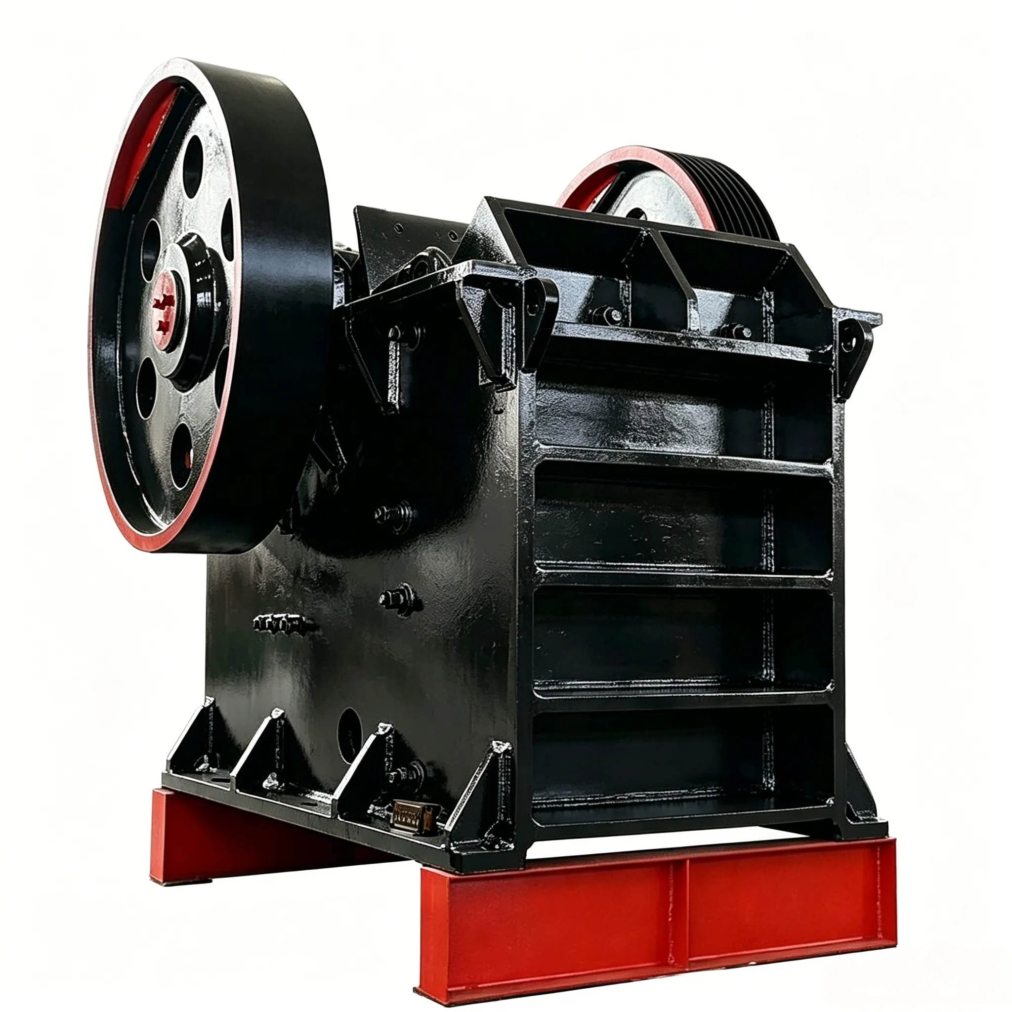
Jaw crushers have been used in industrial production since 1858. Due to their advantages of simple structure, reliable operation, ease of manufacture and maintenance, as well as low management and equipment costs, they are still widely used today in industries such as mineral processing, building materials, silicates, and chemicals. They are used for coarse and medium crushing of hard and medium-hard ores or stones, and small-scale jaw crushers are also used for fine crushing.
The fixed jaw (1 in Figure 2-1) and the movable jaw (2) of a jaw crusher form the crushing chamber. The ore fed into the crushing chamber is crushed, split, and bent by the reciprocating swinging motion of the movable jaw driven by the rotating eccentric shaft (4). When the movable jaw moves away from the fixed jaw, the ore at the lower part of the crushing chamber that has already been crushed to a size smaller than the discharge opening is discharged by gravity through the discharge opening. The ore at the upper part of the crushing chamber, which has not yet been crushed to a size smaller than the discharge opening, only descends a certain distance as the material is discharged. Then, when the movable jaw swings back toward the fixed jaw, the ore that has descended in the crushing chamber is again subjected to further crushing. This process continues until all the ore fed into the crushing chamber is discharged through the discharge opening.

Figure 2-1 Types of jaw crushers
a – complex swing; b – simple swing; c – combined swing
1 – fixed jaw; 2 – movable jaw; 3 – connecting rod; 4 – eccentric shaft; 5 – toggle plate
Depending on the swinging characteristics of the movable jaw, jaw crushers can be classified into three types: those with a simple swinging motion of the movable jaw (Figure 2-1b), those with a complex swinging motion (Figure 2-1a), and those with a combined swinging motion (Figure 2-1c). Currently, the first two types are more widely used.
In a simple swing jaw crusher, every point on the movable jaw moves in an arc. The arc is smaller at the top and larger at the bottom, resulting in relatively low crushing efficiency. However, because this type uses a crank double-link mechanism, although the movable jaw experiences large crushing forces, the eccentric shaft and connecting rod are subjected to smaller forces. Therefore, it can be manufactured as large- and medium-sized crushers for crushing hard ores, with a crushing ratio of i = 3–6.
In a complex swing jaw crusher, the movable jaw itself serves as the connecting rod of the crank-connecting rod mechanism. As a result, every point on the movable jaw moves in an ellipse, and the ellipses become larger from top to bottom. Because the eccentric shaft rotates counterclockwise, the motion direction of each point on the movable jaw promotes ore discharge. Moreover, the horizontal stroke of the movable jaw increases from bottom to top, leading to higher crushing efficiency. Consequently, its productivity is 20%–30% higher than that of a simple swing jaw crusher of the same specification. However, during the crushing process, the grinding and stripping action between the jaw plates and the ore causes faster wear of both the movable and fixed jaw plates, generates more dust, and consumes more energy. In addition, because the movable jaw is directly mounted on the eccentric shaft, the shaft is subjected to large forces. Therefore, the complex swing jaw crusher is suitable for medium- and small-sized machines for crushing medium-hard ores, and its crushing ratio i can reach up to 10. In recent years, with advances in mechanical engineering, compound pendulum jaw crushers have also been developing toward larger sizes.
Jaw crushers produced in China amount to as many as 15 series and over 300 specifications. According to the feed opening width, they can be classified as: large type – greater than 600 mm; medium type – 300–600 mm; small type – less than 300 mm. The technical parameters of the main domestic jaw crusher series are listed in Table 2-1. An example of the model specification interpretation is as follows:

Table 2-1 Technical performance and parameters of jaw crushers
| Modelo | specification | max feed size/mm | output size/mm | capacity/m³,h-¹ | shaft speed /m·min-1 | power/kW | weigh/kg |
| Compound pendulum coarse crusher | PEF250×400 | 210 | 20-60 | 3-13 | 300 | 15 | 3000 |
| PEF400×600 | 340 | 40~100 | 10~40 | 275 | 30 | 6800 | |
| PEF480×600 | 400 | 90-140 | 35-60 | 275 | 37 | 7200 | |
| PEF350×750 | 290 | 70-120 | 30~65 | 300 | 45 | 8975 | |
| PEF350×1000 | 290 | 70~120 | 40-85 | 300 | 55 | 10770 | |
| PEFS00×750 | 425 | 50-100 | 34-68 | 275 | 55 | 11320 | |
| PEF600×750 | 480 | 150~200 | 50-100 | 275 | 55 | 12000 | |
| PEF600×900 | 480 | 75~200 | 32~120 | 255 | 75 | 17600 | |
| PEF700×900 | 560 | 195-245 | 120~180 | 255 | 90 | 18800 | |
| PEF⁷50×1060 | 630 | 75-200 | 75-150 | 255 | 90 | 26000 | |
| PEF750×1200 | 650 | 80-160 | 96~200 | 210 | 110 | 42632 | |
| PEF800×1100 | 650 | 80~200 | 80~160 | 250 | 90 | 29600 | |
| PEF900×1060 | 700 | 230-350 | 218~300 | 250 | 110 | 32600 | |
| PEF900×1200 | 750 | 95-220 | 140~280 | 200 | 132 | 50000 | |
| PEF1000×1200 | 850 | 195~265 | 200~350 | 200 | 185 | 52600 | |
| PEF1200×1500 | 1020 | 150-300 | 270-500 | 180 | 200 | 88000 | |
| PEF1300×1500 | 1120 | 250~400 | 400~700 | 180 | 250 | 96000 | |
| PEF1500×2100 | 1250 | 300-450 | 350~620 | 150 | 245 | 152000 |
| Modelo | Especificación | max feed size/mm | output size/mm | capacity/m³ ·h-¹ | shaft speed /m·min⁻¹ | power/kW | weigh/kg |
| Compound pendulum fine crushing type | PEX150×500 | 125 | 10~40 | 5-12 | 300 | 11 | 2470 |
| PEX150×750 | 125 | 10~40 | 5~15 | 300 | 15 | 3600 | |
| PEX250×750 | 210 | 10~50 | 8~22 | 300 | 22 | 5890 | |
| PEX200×1000 | 160 | 10~50 | 9~25 | 300 | 22 | 6800 | |
| PEX250×1000 | 210 | 15~55 | 10~32 | 300 | 30 | 7350 | |
| PEX250×1200 | 210 | 15-60 | 12~38 | 300 | 37 | 8700 | |
| PEX300×1300 | 250 | 20~90 | 15-65 | 300 | 75 | 11600 | |
| PEX400×750 | 320 | 15-50 | 12-40 | 300 | 37 | 9510 | |
| PEX400×1200 | 340 | 20~80 | 18-60 | 330 | 55 | 11278 | |
| Simple swing type | PE900×1200 | 750 | 100-180 | 120-200 | 180 | 110 | 62000 |
| PE1200×1500 | 850 | 130~180 | 130-200 | 135 | 180 | 128000 | |
| PE1500×2100 | 1250 | 170-220 | 400-500 | 100 | 260280 | 220000 |
Construction of a Simple Swing Jaw Crusher
Figure 2-2 shows the structure of a 900 mm × 1200 mm simple swing jaw crusher. As can be seen from the figure, the front wall of the crusher frame (1) serves as the fixed jaw. To prevent wear, a jaw plate (2) is fixed onto it. The shaft (4) is supported at both ends by bearings, and the movable jaw (5) along with its jaw plate (6) is suspended on this shaft.

Figure 2-2 – 900 mm × 1200 mm simple swing jaw crusher
1 – frame; 2,6 – jaw plates; 3 – pressing plate; 4 – shaft; 5 – movable jaw; 7 – wedge; 8 – eccentric shaft; 9 – connecting rod head; 10 – belt pulley; 11 – elbow plate; 12 – front toggle plate; 13 – rear toggle plate; 14 – rear support seat; 15 – tie rod; 16 – spring; 17 – shim pack; 18 – flat liner plate; 19 – steel plate
The eccentric shaft (8) is supported on main bearings, and the connecting rod head (9) is mounted on the eccentric shaft. The connecting rod head is manufactured separately from the rod body and then tightly fastened together with screws. Circulating cooling water is passed through the interior of the connecting rod head to cool its bearing bush. The motor drives the belt pulley (10), which is fixed on the eccentric shaft, via V-belts, causing the eccentric shaft to rotate. Grooves on both sides of the lower part of the rod body accommodate the elbow plate (11), and one end of each of the front and rear toggle plates (12 and 13) is supported on the elbow plate.
The tie rod (15) pulls the lug at the lower end of the movable jaw, and its other end is supported against the rear wall of the frame by a spring (16). When the movable jaw swings forward and then backward, the inertial forces generated by the movable jaw and the toggle plates are balanced by the spring through the tie rod, thus keeping the movable jaw, toggle plates, and connecting rod in close contact without impact. In addition, the tie rod (15) is supported from below by a roller, preventing it from being worn by the spring support plate.
Apart from the belt pulley (10) fixed at one end of the eccentric shaft, a flywheel is fixed at the other end; the belt pulley also acts as a flywheel. During the idle stroke of the crusher, the flywheel stores energy, and during the working stroke, it releases energy, thereby reducing the unevenness of the eccentric shaft’s rotational speed and ensuring a stable and balanced power output from the motor.
A set of shims (17) is placed between the elbow plate of the rear toggle plate and the rear support seat (14) to adjust the size of the discharge opening. Increasing the thickness of the shim pack (17) moves the movable jaw forward by a certain distance, reducing the discharge opening. Conversely, decreasing the thickness of the shim pack increases the discharge opening accordingly.
The rear toggle plate (13) also serves as a safety element. When uncrushable material mixed with the ore enters the crushing chamber, the forces on the various components may exceed the permissible material strength. To prevent damage to other components, the crusher is generally designed so that the rear toggle plate, which is relatively simple in shape and smaller in size, has a lower strength, allowing it to act as a safety device.
The jaw plates of the movable jaw and the fixed jaw have a wavy surface. The crest of one jaw plate faces the trough of the other, which subjects the ore to bending forces and thus improves crushing efficiency.
Manganese steel flat liner plates (18) are fitted on the side walls of the crushing chamber and are fixed to the side walls with screws or wedges. To prevent the liner plates from moving up and down due to friction between the ore and the liner plates (which could shear the screws), the fixed jaw plate is not only secured with screws but also supported at its lower end on the steel plate (19) and pressed at its upper end by the pressing plate (3). The steel plate (19) is welded to the frame. The lower end of the movable jaw plate rests on a boss at the bottom of the movable jaw, and its upper end is pressed down by the wedge (7).
The crusher uses two types of bearings: plain bearings lined with Babbitt metal and those with copper-alloy bushes. The bearings of the movable jaw and the supports of the toggle plates (12 and 13) are lubricated with grease. The bearings of the eccentric shaft and the connecting rod head are lubricated by forced circulation of thin oil.
Construction of a Segmented-Start Simple Swing Jaw Crusher
Figure 2-3 shows a 1200 mm × 1500 mm segmented-start jaw crusher. Its construction is basically the same as that of the 900 mm × 1200 mm simple swing jaw crusher shown in Figure 2-2. The main differences are as follows:
(1) The toggle plate of the 1200 mm × 1500 mm segmented-start jaw crusher is an assembly consisting of a toggle head and a flat plate connected by screws. When the toggle head needs to be replaced, the flat plate can be retained; when the flat plate is damaged and requires replacement, the toggle head can be retained.
(2) This machine can be started in three stages.
Hydraulic friction clutches are mounted on both ends of the eccentric shaft (Figure 2-4). When the crusher is overloaded, an overcurrent relay activates a time-delay relay, which starts the hydraulic pump motor to disengage the clutches and simultaneously cuts off the main motor, thereby providing overload protection.
The crusher’s pulley and flywheel are connected to the eccentric shaft via friction clutches. The friction clutches are controlled by a hydraulic system. During startup, the hydraulic pump motor is first started, allowing pressurized oil to flow through the central passage of the piston into the right side (pulley side) or left side (flywheel side) of the piston. This pushes the piston, compressing the springs of the friction clutch plates and separating the friction plates, thus disengaging the connection between the eccentric shaft and the pulley or flywheel. At this point, the electric motor can be started to rotate the pulley. Then, through a solenoid directional valve, the friction clutch between the pulley and the eccentric shaft is first engaged, causing the eccentric shaft and connecting rod to begin moving. Subsequently, the friction clutch between the eccentric shaft and the flywheel is engaged, causing the flywheel to rotate. The crusher starts and operates in the three-stage sequence described above.
2.3 Construction of the Segmented-Start Simple Swing Jaw Crusher


Figure 2-3 Structure of the 1200 mm × 1500 mm segmented-start jaw crusher
1, 2 – Hydraulic friction clutches

Figure 2-4 Hydraulic friction clutch
1 – oil plug; 2 – oil collector; 3 – bushing; 4 – bearing liner; 5 – clamping frame; 6 – oil pipe; 7 – cover; 8 – clamping spring; 9 – friction plate; 10 – piston; 11 – hydraulic cylinder; 12 – belt pulley; 13 – frame; 14 – bearing cap; 15 – eccentric shaft; 16 – connecting rod head; 17 – connecting rod
(flywheel side) – pushes the piston to compress the springs of the friction clutch plates, separating the friction plates and disengaging the connection between the eccentric shaft and the pulley or flywheel. At this point, the electric motor can be started to rotate the pulley. Then, through a solenoid directional valve, the friction clutch between the pulley and the eccentric shaft is first engaged, causing the eccentric shaft and connecting rod to begin moving. Subsequently, the friction clutch between the eccentric shaft and the flywheel is engaged, causing the flywheel to rotate. The crusher starts and operates in the three-stage sequence described above.
Jaw crushers of other specifications use single-stage starting, i.e., as soon as the main motor is started, the entire transmission system moves. Because the oscillating masses of large jaw crushers (such as the connecting rod and movable jaw) have large inertia, the motor’s starting power consumption is relatively high, often three times the normal crushing power. This requires a large installed motor power, but after starting, the motor runs underloaded, resulting in a low power factor on the power grid. For large jaw crushers, installing two sets of hydraulic friction clutches for three-stage starting makes starting easier and reduces the required installed motor power. This is technically reasonable and economically advantageous.
Construction of a Complex Swing Jaw Crusher
Figure 2-5 shows the structure of a complex swing jaw crusher. In this type of crusher, the movable jaw (11) also serves as the connecting rod, so its mechanism is correspondingly simplified.
The movable jaw (11) of the crusher is directly suspended on the eccentric shaft (10) using roller bearings, while the eccentric shaft itself is supported in roller bearings mounted in the frame (12). When the motor drives the belt pulley (13) fixed on the eccentric shaft via V-belts, the eccentric shaft causes the movable jaw to perform a complex swinging motion. A toggle plate (4) is fitted into a groove at the lower end of the movable jaw, and both ends of the thrust plate (5) are supported on toggle plates. The rear toggle plate is installed in the front wedge block (6), which rests in sliding grooves on both side walls of the frame and is in close contact with the rear wedge block (7). When the discharge opening needs to be adjusted, turning the nut that holds the rear wedge block (7) clockwise raises the rear wedge block, pushing the front wedge block forward along the sliding grooves, thereby reducing the discharge opening. Turning the nut in the opposite direction increases the discharge opening.
The other parts of this crusher are similar to those of the simple swing jaw crusher. Its construction features are: both the movable jaw bearing and the eccentric shaft bearing are roller bearings, providing high transmission efficiency and simple lubrication; the thrust plate head and the toggle plate are in rolling contact, which reduces wear.

Figure 2-5 250 mm × 400 mm complex swing jaw crusher
1 – Fixed jaw liner plate 2 – Side guard plate 3 – Movable jaw liner plate 4 – Toggle plate (elbow plate) 5 – Thrust plate 6 – Front wedge block 7 – Rear wedge block 8 – Tie rod 9 – Flywheel
10 – Eccentric shaft 11 – Movable jaw 12 – Frame 13 – V-belt pulley
Construction of a Complex Swing Jaw Crusher
Figure 2-5 shows the structure of a complex swing jaw crusher. In this type of crusher, the movable jaw (11) also serves as the connecting rod, so its mechanism is correspondingly simplified.
The movable jaw (11) of the crusher is directly suspended on the eccentric shaft (10) using roller bearings, while the eccentric shaft itself is supported in roller bearings mounted in the frame (12). When the motor drives the belt pulley (13) fixed on the eccentric shaft via V-belts, the eccentric shaft causes the movable jaw to perform a complex swinging motion. A toggle plate (4) is fitted into a groove at the lower end of the movable jaw, and both ends of the thrust plate (5) are supported on toggle plates. The rear toggle plate is installed in the front wedge block (6), which rests in sliding grooves on both side walls of the frame and is in close contact with the rear wedge block (7). When the discharge opening needs to be adjusted, turning the nut that holds the rear wedge block (7) clockwise raises the rear wedge block, pushing the front wedge block forward along the sliding grooves, thereby reducing the discharge opening. Turning the nut in the opposite direction increases the discharge opening.
The other parts of this crusher are similar to those of the simple swing jaw crusher. Its construction features are: both the movable jaw bearing and the eccentric shaft bearing are roller bearings, providing high transmission efficiency and simple lubrication; the thrust plate head and the toggle plate are in rolling contact, which reduces wear.


