
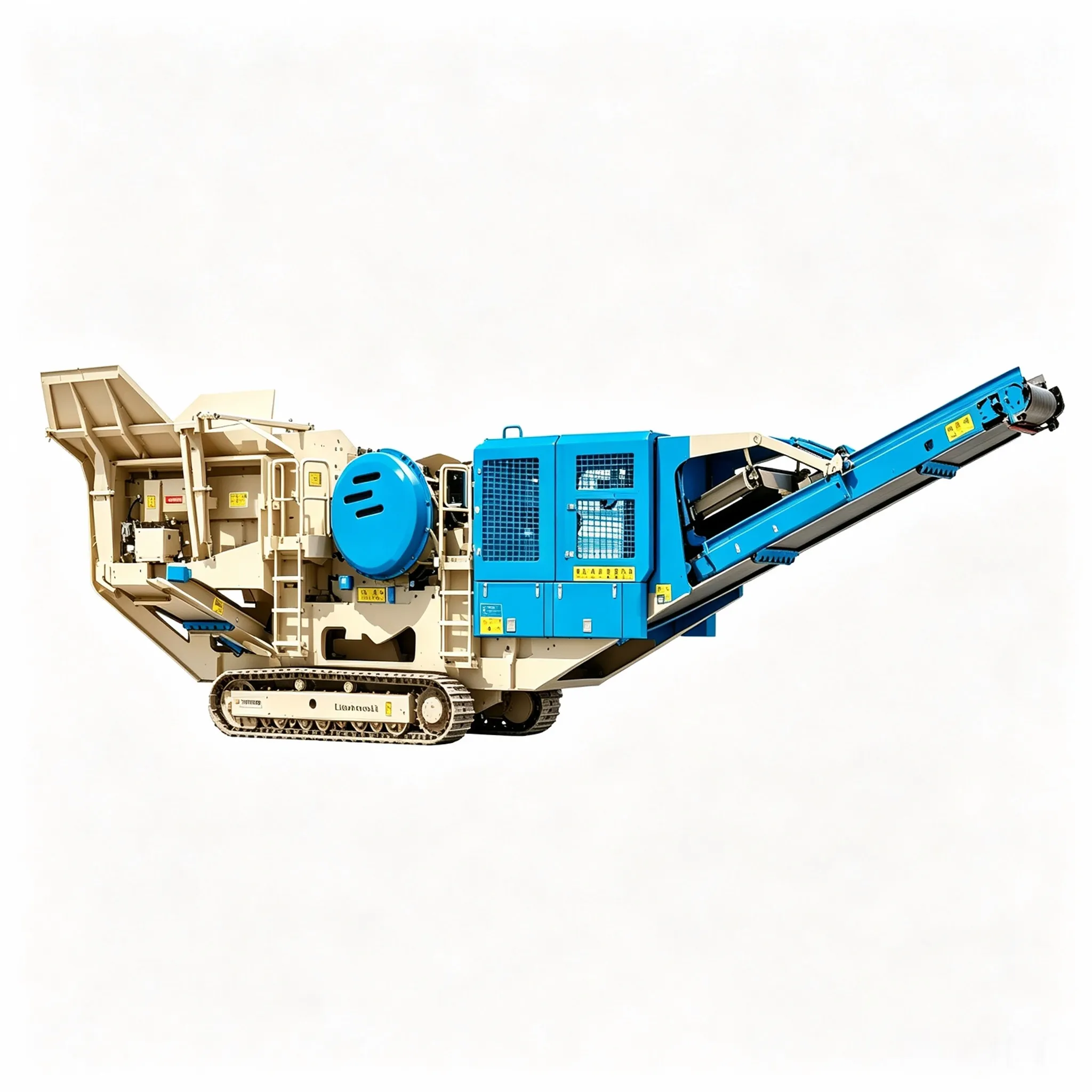
小型移動式砕石機
はじめに ミニ移動式ジョークラッシャーは、極めてコンパクトな、クローラー式破砕機であり…

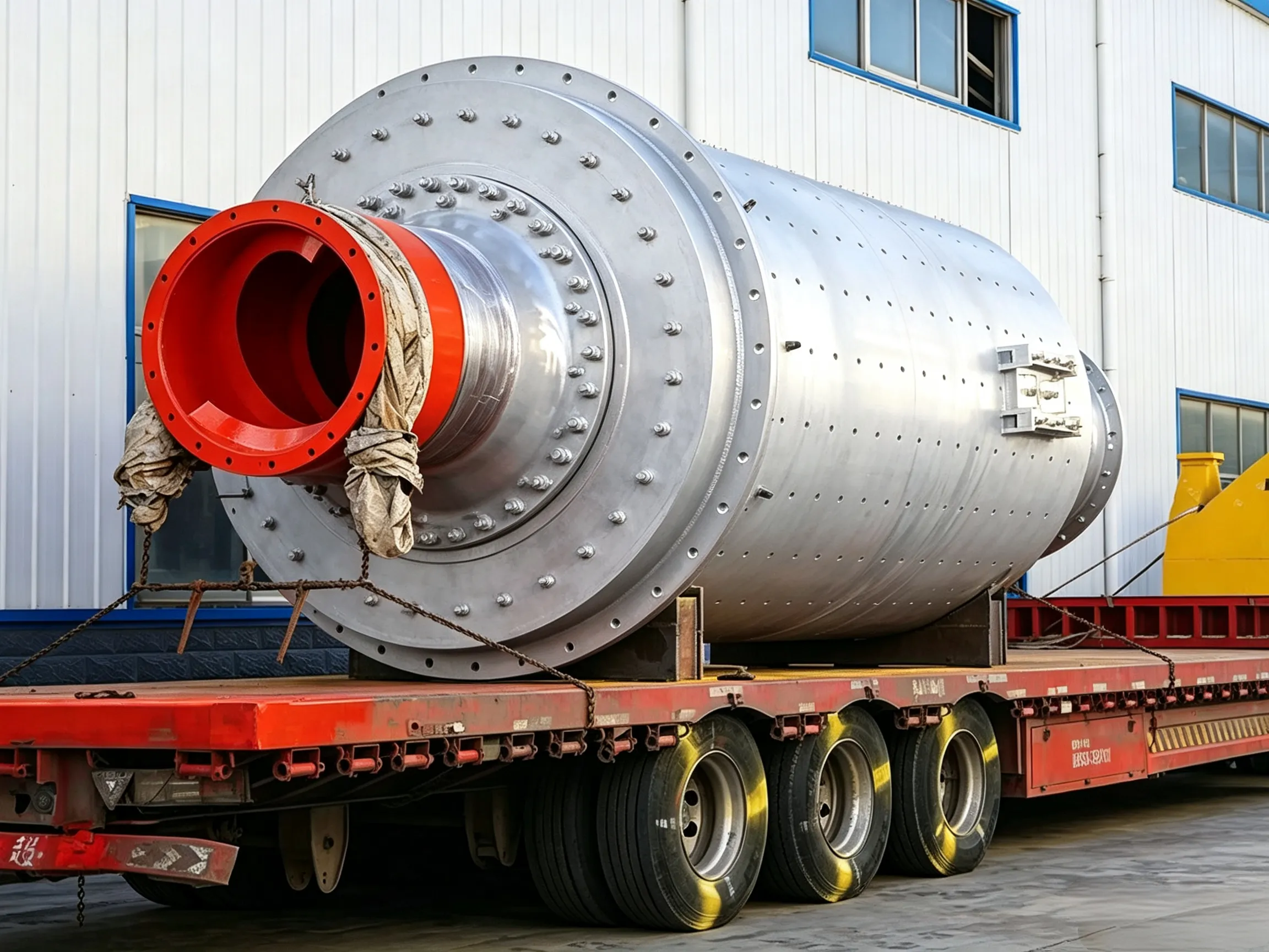
① Excessive ovality or excessive cylindricity error of the hollow shaft journal, with deep concave‑convex marks on the surface, and even cracks or holes.
② Axial cracking of the hollow shaft, with cracks extending along the axial direction from the center toward both ends. In severe cases, the cracks penetrate the shaft wall. Typically, the cracks are not perpendicular to the center but are irregularly slanted.
③ Severe wear of the inner bore of the hollow shaft, with an increase in inner diameter. In some cases, the maximum wear exceeds 50%.
(2) Cause analysis
After long‑term operation, the hollow shaft naturally undergoes wear due to material fatigue. However, occasional poor maintenance can also aggravate the wear. For example, if a small amount of material enters the gap between the inner bore of the feed‑end hollow shaft and the spiral cylinder, it can cause severe wear of the inner bore. If such wear reaches a certain level and is not detected and repaired in time, cracks, holes, and other defects may develop, affecting the continuous operation of the mill. Repair must then be carried out.
(3) Treatment methods
① Repair of worn areas on the hollow shaft journal surface
a. Remove the hollow shaft or the mill head and place it on a large vertical lathe for turning repair. If the hollow shaft journal has cracks, first determine the exact start and end points of all cracks (using flaw detection instruments and visual inspection, including hidden cracks). Repair them by weld build‑up, and then perform turning. The specific accuracy requirements shall be determined according to the original drawings. After turning, the journal must be ground after the mill head is installed.
b. After weld repair, carry out machining using an additional temporary support and tool post set up on site, or use the original journal support for machining. First, select a relatively good area (surface C) of the journal as the support surface, and turn surface D. Then use the machined surface D as the support surface to turn surface C, as shown in Figure 2.34.

Figure 2.35 Schematic diagram of repairing the journal surface by machining using the original journal support
The requirements for the tool post and the shell position are as follows: the centerline B of the tool post shall be parallel to the centerline A of the shell; the longitudinal feed and cross feed of the tool post shall be perpendicular to each other. The shell remains supported on the original main bearings, and axial movement of the shell shall be restricted before machining.
During the repair process, if the bearing cannot be lubricated normally, temporary lubrication measures must be taken. After turning, the journal must be ground after the mill head is installed. If the hollow shaft journal has cracks, all cracks shall be identified, repaired by weld build-up first, and then turning shall be carried out until the repair requirements are met.
② Repair methods and procedures for axial cracking of the hollow shaft
a. Rotate the mill so that the crack stays at the top dead center. The mill shall not be rotated throughout the entire repair process.
b. Cut a bevel using an oxy-acetylene flame. The bevel shape shall be an arc-stepped form. The bevel length shall be 60 mm longer than the visible crack, with 30 mm on each end.
c. After bevel cutting is completed, remove the slag and weld immediately. The temperature of the hollow shaft shall be maintained at about 200 °C. Use manual DC arc welding. For the bottom layer, use φ3.2 mm electrodes with a current of 140 A; then use φ4 mm electrodes with a current of 160 A until capping. The weld shall be 2 mm above the base metal. During welding, weld both sides first, and hammer while welding to relieve part of the stress (when the hollow shaft material is ZG45 medium carbon steel, 507 structural steel electrodes give good results).
d. After the outer weld is completed, cut a small bevel on the inner weld with a depth of 5 mm, then weld again, with the weld 3 mm above the base metal.
e. After all welding is completed, place charcoal in a specially made iron box and perform heat treatment on the welded area. Heat treatment shall be carried out simultaneously on both the inner and outer walls. One end of the iron box is made of perforated plate to allow air inflow for charcoal combustion. After heat treatment is completed, cover with 4–5 layers of burlap bags and hold for 5 hours for heat preservation.
f. File off the part of the weld on the outer diameter of the hollow shaft that protrudes above the base metal, then grind with an oilstone or manual grinder. Inspect using a turned template, and finally measure the welded area at various points along the circumferential direction with calipers until the technical requirements are met.
③ Severe wear of the inner bore of the hollow shaft can be repaired by the inlaid bushing method (Figure 2.36). The procedure is as follows:
a. Roll a 14‑mm‑thick steel plate into a cylinder. The cylinder diameter depends on the degree of wear and the diameter of the hollow shaft.
b. Cut the steel cylinder into 3 pieces, and press‑fit and weld them firmly onto the inner bore of the hollow shaft.
c. Fill the gap between the steel plate and the shell wall with asbestos rope or waste cloth.
d. Weld the tail end of the spiral cylinder and the hollow shaft together using a baffle plate, which can prevent further wear of the inner bore of the hollow shaft.
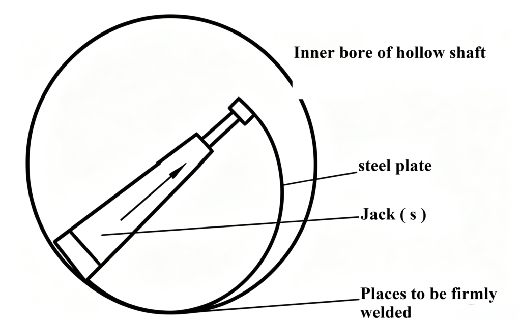
Figure 2.36 Schematic diagram of hollow shaft inlaid bushing installation
④ Maintenance quality requirements
a. The material of the hollow shaft shall comply with the following provisions:
b. Surface roughness and flaw detection quality shall not be lower than the requirements specified in Table 2.10.
Table 2.10 Surface roughness and flaw detection quality for hollow shaft bearings
| part name | Roughness R. (μm) | Flaw detection quality | |
| Hollow shaft root fillet area | outer side | 1.6 | A. Ultrasonic flaw detection shall be conducted on the interior of steel castings, and it shall be qualified according to Level I specified in GB/T 7233.B. The interior of the weld seam shall comply with the “General Technical Conditions for Steel Welding Parts of Building Materials Machinery” (JC/T 532—The provisions of Appendix A in (2007) or the Level II provisions in “Radiographic Testing of Fusion Welded Butt Joints in Metallic Materials” (GB/T 3323—2005).C. The surface shall meet the requirements of Level 2 specified in “Penetrant Testing of Steel Castings” (GB/T 9443-2007) or “Magnetic Particle Testing of Steel Castings” (GB/T 9444-2007) |
| medial side | 6.3 | ||
| Hollow shaft journal, shaft shoulder fillet area | 1.6 | ||
c. Tolerance of hollow shaft:
The tolerance for the journal diameter is Class h3 according to GB 1802;
The diameter tolerance of the flange locating circle is Class f9 according to GB 1802;
The coaxiality tolerance of the flange locating circle to the journal circle is Grade 7 according to “Geometrical Tolerancing – Geometrical Tolerance for Features without Individual Tolerance Indications” (GB/T 1184-1996);
The perpendicularity tolerance of the flange end cover to the journal axis is Grade 7 according to “Geometrical Tolerancing – Geometrical Tolerance for Features without Individual Tolerance Indications” (GB/T 1184—1996);
The positional tolerance of the flange bolt holes is φ1mm.
d. When the chipping area exceeds 6% of the area of the surface where the defect is located and the crack is in an important position, welding repair is not allowed; when the chipping area does not exceed 6% of the area where the defect is located and the chipping width does not exceed 10% of the width of the surface where the defect is located, welding repair is allowed for defects in hollow shafts.
e. After finishing, the number of air holes within 3mm×3mm on the journal surface of the hollow shaft shall not exceed 5, and the spacing between air holes shall not be less than 150mm. All air holes must be trimmed smooth and free of edge marks, and the roughness R of the trimmed surface shall not exceed 1.6μm.
f. After the hollow shaft is assembled with the cylinder, the relative radial circular runout tolerance of the hollow shaft journals at both ends is 0.2 mm.
g. The radial circular runout tolerance of the large gear to the hollow shaft journal shall not exceed 0.25/1000 of the pitch diameter, and the end face runout shall not exceed 0.35/1000 of the pitch diameter.
h. The radial circular runout tolerance of the cylindrical surface of the sealing friction part for material feeding and discharging, relative to the hollow shaft journal, is 0.5 mm.
i. For the mating contact between the hollow shaft journal and the spherical tile, refer to Table 2.11.
Table 2.11: Fit Clearance (mm)
| Hollow shaft diameter | 800 | 900 | 1000 | 1200 | 1400 | 1600 | 1800 | 2000 | 2240 |
| Side clearance | 0.12~0.19 | 0.14~0.21 | 0.16~0.23( | 0.21~0.28 | 0.24~0.32 | 0.25~0.35 ( | 0.29~0.41 | 0.34~0.46 | 0.39~0.54 |
 English English
 Spanish
 Russian
 Arabic
 Swahili
 French
 Turkish
 Portuguese
 Korean
 Japanese
 German
 Italian