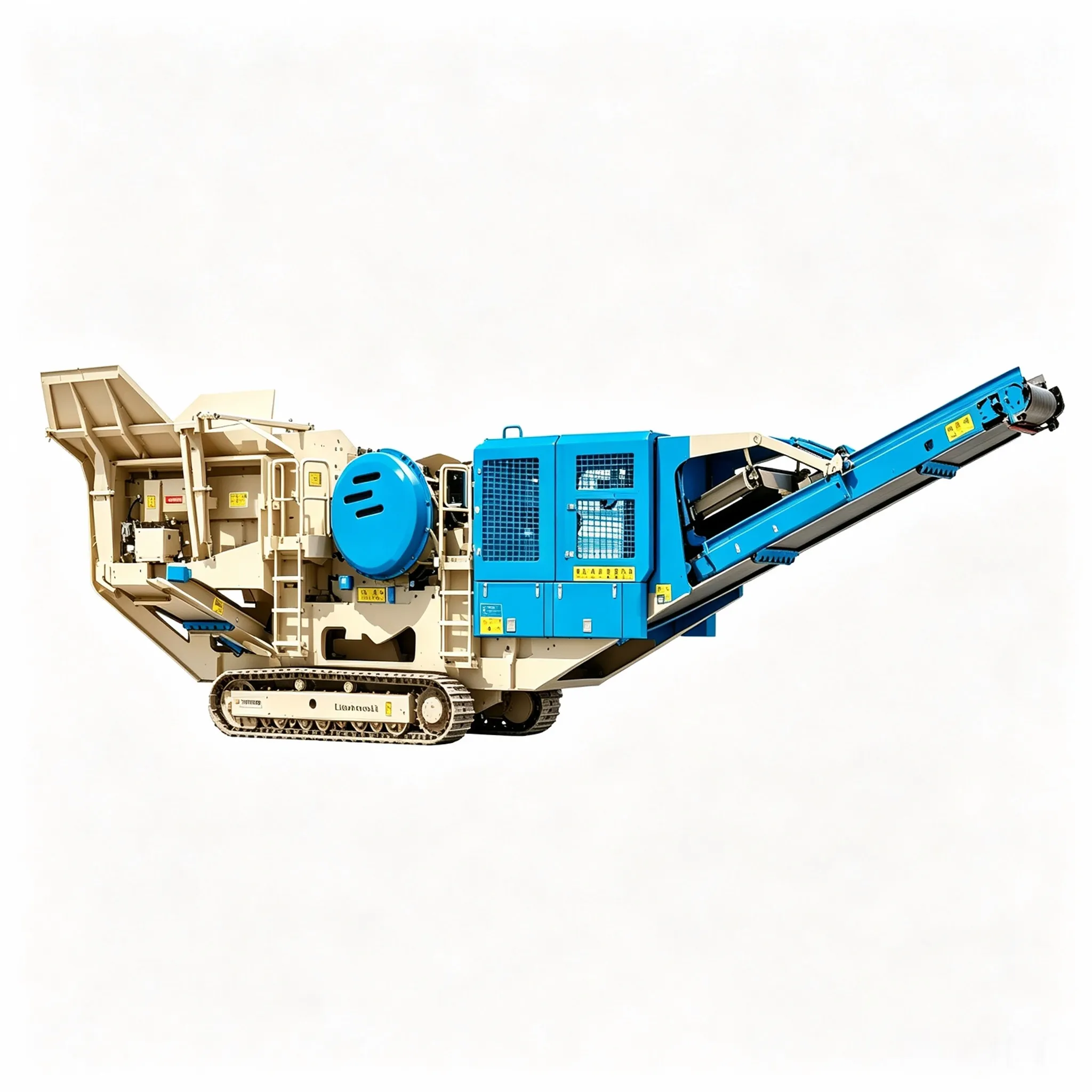
クローラー式移動式砕石機
移動式ジョークラッシャーステーション シリーズ 標準モデル 搭載機器 搭載機器 処理能力(t/h) 輸送寸法(mm)…

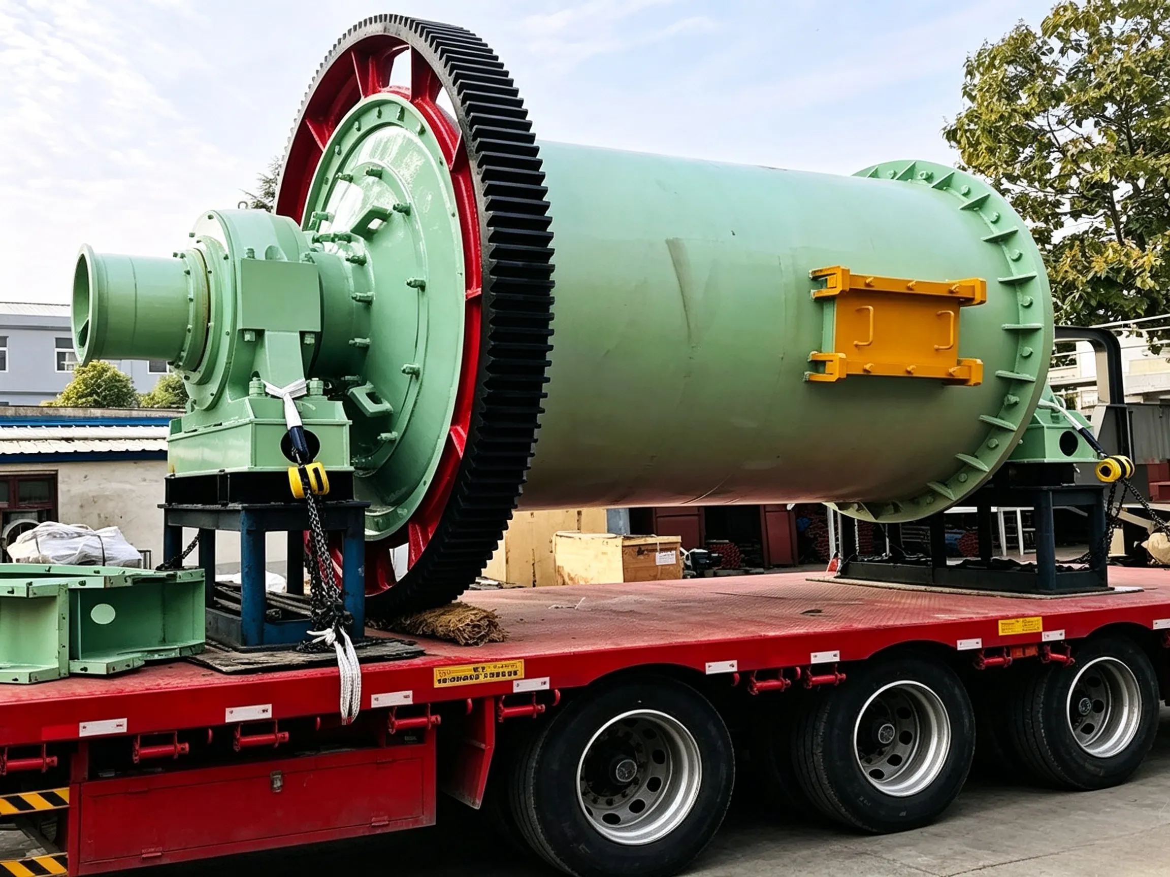
There are two installation methods: the bolt fixing method and the brick‑laying (embedding) method.
The bolt fixing method is used for all compartments of tube mills. The following precautions should be observed during installation:
① Directional liners (such as stepped liners, classifying liners, etc.) must be installed with their direction matching the mill rotation direction and material flow requirements. For example, the thin end of a stepped liner must face the direction of mill rotation.
② The liners should be arranged in a staggered pattern to avoid forming circumferential gaps. The entire circumferential gap at the junctions between liners and the intermediate diaphragm or the material retaining ring must be eliminated using wooden or steel wedges. For wet mills, a layer of rubber sheet or plywood should be placed underneath the liners. A gap of 5–10 mm should be left between adjacent liners. If the gap is too small, thermal expansion and deformation of the liners due to impact and friction may cause the bolts or the liners themselves to fracture; if the gap is too large, the shell may become worn.
③ The gap between the liners and the shell must be filled with cement mortar (mix ratio 1:1, using Grade 42.5 cement). When tightening the liner bolts, excess cement mortar should be squeezed out. 24 hours after installation, the bolts should be tightened again. When tightening, force should be applied evenly, and striking the wrench handle with a hammer is prohibited. The bolts should pass freely through the liners and the shell. After tightening, the bolt heads must be recessed into the countersunk holes of the liners and tightened to the limit. In the rod compartment of a rod‑ball mill, the bolt heads must not protrude beyond the working surface of the liners, so as not to affect the movement of the rods.
④ Between the outer surface of the mill shell and the nuts, sealing packing and heat‑resistant rubber gaskets (or asbestos gaskets) should be placed to prevent powder or slurry from leaking out through the bolt holes. Lock washers or double nuts should be used to prevent the bolts from loosening.
⑤ Rubber liners: Rubber sheets are stored and transported in rolled form. They should be unrolled and laid flat 3–4 weeks before use to allow free elongation. During installation, the long side of the rubber sheet should be oriented axially (the short side circumferentially). After installation, the circumferential seams of adjacent rubber sheets must not be aligned (i.e., the joints must be staggered). Any protruding points at the contact areas between the liners and the mill head or the intermediate diaphragm should be ground smooth. After the bolts are tightened, axial movement must be prevented. The liners must be tightened to the specified torque (neither too high nor too low). The installation method for rubber liners is essentially a bolt fixing method. A flexible connection is adopted, and no installation gaps are left; two liner plates are pressed down by one rubber holding‑down strip. The strip is secured by a bolt passing through the shell via a “T”‑shaped pressing plate, fitted with a washer, then pressed tightly with a butterfly‑shaped gland and secured with a nut. The “T”‑shaped pressing plate and the bolt shank are welded into one piece. Because the pressing plate is deeply embedded in the holding‑down strip, the plate and bolt are not directly worn by the grinding media and material.
The brick‑laying method is used for fixing liners in the third and fourth compartments of long tube mills, and can also be used for fixing liners in the fine‑grinding compartment of medium‑long tube mills. The following precautions should be observed:
① Before installation, each liner must be inspected for quality. The inner and outer arc surfaces of the liners should be concentric; the contact surfaces between the liners and the shell must have no raised portions; protrusions on the circumferential side faces of the liners should be less than 1.5 mm (if exceeding this, they should be ground with an abrasive wheel) so that the liners fit tightly against the inner surface of the shell and against each other circumferentially; any casting defects in the liners must not affect the liner strength; and the liner material must comply with technical requirements.
② Before installing brick‑laid liners, the intermediate diaphragm and the discharge grate plate should be installed first; if the mill has a material retaining ring, it should also be installed first; the manhole liners should also be installed first, and the manhole should be rotated to the lowest position.
③ Installation procedure: First, spread a uniform layer of 1:1 cement mortar on the inner wall of the shell. Then, lay the liners circumferentially one tightly against the other on the cement mortar. During installation, tap firmly with a hand hammer so that excess cement mortar is squeezed out through the through‑holes of the liners. After the lower half‑circumference of the entire compartment has been laid, use supporting props to secure the liners (one prop supporting the two liners at its ends, with wooden padding placed between both ends of the prop and the liners). Then, slowly rotate the shell by 45° and complete the liners in this angular zone. After that, rotate the shell by another 45° and lay the liners in that zone. After completing this zone, install another supporting prop (perpendicular to the previous one). Proceed in this manner until all liners in the mill are installed. After completion, the mill must be cured for at least 2 days before starting up.
During brick‑laying installation, quality should be checked at all times to prevent the liners from arching or losing contact with the shell. The cement used should have early‑strength properties, and it is advisable to add an appropriate amount of early‑strength agent. The liners should be arranged in a staggered pattern with 5–10 mm gaps between them. Each liner must be firmly set in place (especially at the head and tail of each row of liners and at the joints of the two semi‑circular arches); if necessary, they should be welded securely using the build‑up welding method.


 English English
 Spanish
 Russian
 Arabic
 Swahili
 French
 Turkish
 Portuguese
 Korean
 Japanese
 German
 Italian