
Molino de impacto ultramicro de la serie SCR
Molino de impacto ultramicro de la serie SCR El molino de impacto de la serie SCR es un...
According to the ways by which motion is imparted to the charge, grinding mills are generally classified into two types: tumbling mills and stirred mills. In tumbling mills, the mill shell is rotated and motion is imparted to the charge via the mill shell. The grinding medium may be steel rods, balls, or rock itself. Media ball sizes, for example, range from about 20mm for fine grinding to 150mm for coarse grinding. Tumbling mills are typically employed in the mineral industry for primary grinding, in which particles between 5mm and 250mm are reduced in size to between 25μm and 300μm. In stirred mills, the mill shell is stationary mounted either horizontally or vertically and motion is imparted to the charge by the movement of an internal stirrer. Grinding media (25mm or less) inside the mill are agitated or rotated by the stirrer, which typically comprises a central shaft to which are attached screws, pins, or discs of various designs. Stirred mills find application in regrinding, fine (15-40μm) and ultrafine (-15μm) grinding.
Tumbling mills are of three basic types: rod, ball, and autogenous/semi-autogenous (AG/SAG), based on the type of grinding media (SAG mills are AG mills with some grinding balls). Structurally, each type of mill consists of a horizontal cylindrical shell, provided with renewable wearing liners and a charge of grinding medium. The drum is supported so as to rotate on its axis on hollow trunnions attached to the end walls. The diameter of the mill determines the impact that can be exerted by the medium on the ore particles and, in general, the larger the feed size the larger the mill diameter needs to be. The length of the mill, in conjunction with the diameter, determines the volume, and hence the capacity of the mill.
Rod mills and ball mills are classed according to the nature of the discharge. The most widely used type of rod mill in the mining industry is the trunnion overflow (Fig.5.9), in which the feed is introduced through one trunnion and discharges through the other. A flow gradient is provided

by making the discharge (overflow) trunnion diameter 10-20cm larger than that of the feed opening. The discharge trunnion is often fitted with a spiral (trommel) screen to remove tramp material.
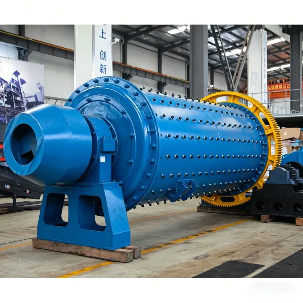
The final stages of primary comminution are performed in tumbling mills using steel balls as the grinding medium, and so are designated “ball mills”. Since balls have a greater surface area per unit weight than rods, they are better suited for fine grinding. The term ball mill is restricted to those having a length to diameter ratio of 2 to 1 and less. Ball mills in which the length to diameter ratio is between 3 and 5 are designated tube mills. The latter are sometimes divided into several longitudinal compartments, each having a different charge composition; the charges can be steel balls or rods, or pebbles, and they are often used dry to grind cement clinker, gypsum, and phosphate. Tube mills having only one compartment and a charge of hard, screened ore particles as the grinding medium are known as pebble mills. They have the advantage over ball mills when iron contamination needs to be avoided. Since the weight of pebbles per unit volume is about 35%-55% of that of steel balls, and as the power input is directly proportional to charge weight, the power draw and capacity of pebble mills are correspondingly lower. Thus, in a given grinding circuit, for a certain feed rate, a pebble mill would be much larger than a ball mill, with correspondingly higher capital cost.
Ball mills may be simple trunnion overflow mills, operated in open or closed circuit, or grate discharge (low-level discharge) mills. The latter type is fitted with discharge grates between the cylindrical mill body and the discharge trunnion. The pulp can flow freely through the openings in the grate and is then lifted up to the level of the discharge trunnion (Fig.5.10). These mills have a lower pulp level than overflow mills, thus reducing the residence time of particles in the mill. Consequently, little overgrinding takes place and the product contains a large fraction of coarse material, which is returned to the mill by some form of classifying device. Grate discharge mills usually take a coarser feed than overflow mills and are not required to grind so finely, the main reason being that with many small balls forming the charge, the grate open area plugs very quickly. The trunnion overflow mill is the simplest to operate and is used for most ball mill applications, especially for fine grinding and regrinding. Energy consumption is said to be about 15% less than that of a grate discharge mill of the same size, although the grinding efficiencies of the two mills are similar.

The highest throughput grinding circuits in the mining industry use autogenous grinding (AG) or semiautogenous grinding (SAG) mills. An AG mill is a tumbling mill that uses the ore itself as grinding media. The ore must contain sufficient competent pieces to act as grinding media and preferably be high specific gravity (s.g.), which, for example, favors AG milling of iron ores (s.g.4 VS.2.7 for high silicate ores). A SAG mill is an autogenous mill that uses steel balls in addition to the natural grinding media. The ball charges in SAG mills have generally been most effective in the range of 4%-15% of the mill volume, including voids. In South African practice SAG mills can have a ball charge as high as 35% of mill volume.
AG/SAG mills usually replace the final two stages of crushing (secondary and tertiary) and rod milling of the traditional circuit. This gives some advantages over the traditional circuit: lower capital cost, ability to treat a wide range of ore type including sticky and clayey feeds, relatively simple flowsheets, large size of available equipment, lower manpower requirements, and reduced steel consumption. The use of AG/SAG milling has grown to the point where many existing plants are retrofitting them, whilst new plants rarely consider a design that does not include them. This may not continue in the future, as new technologies such as fine crushing, high pressure grinding rolls, and ultra fine grinding (stirred milling) offer alternative flowsheet options. A schematic of various sections of the autogenous grinding mill is shown in Fig.5.11. AG or SAG mills are defined by the aspect ratio of the mill shell design and the product discharge mechanism. The aspect ratio is defined as the ratio of diameter to length. Aspect ratios generally fall into three groups: high aspect ratio mills where the diameter is 1.5-3 times of the length, “square mills” where the diameter is approximately equal to the length, and low aspect ratio mills where the length is 1.5-3 times that of the diameter. The largest SAG mills are up to 12m in diameter by 6.1m length, driven by a motor power of more than 20MW. Many high aspect ratio mills, particularly the larger diameter units, have conical rather than flat ends. Attention should therefore be given to the mill length definition. Inside the milling chamber the mill is lined with wearing plates held by lifter bars bolted to the shell. Lifter bars are essential to reduce slippage of the mill load, which causes rapid wear of the liners and also impairs the grinding action. The shape and geometry of the lifter bars, particularly the height and the face angle, have a significant influence on milling performance and wear rates. The grate is used to hold back the grinding media and large rock pieces and allow fine particles and slurry

Schematic of various sections of an AG mill
to flow through. Shapes of the grate apertures can be square, round, or slotted, with size varying from 10mm to 40mm. In some installations there are large holes varying from 40mm to 100mm in the grate, designated as pebble ports, which allow pebbles to be extracted and crushed (to 12-20mm) prior to recirculation to the mill.
The slurry of particles smaller than the grate apertures discharges into the pulp lifter chambers.
The pulp lifters, which are radially arranged, as shown in Fig.5.12, rotate with the mill and lift the slurry into the discharge trunnion and out of the mill. Each pulp lifter chamber is emptied before its next cycle to create a gradient across the grate for slurry transportation from the milling chamber into the pulp lifter chambers. There are two types of pulp lifter design: radial and curved, also known as spiral, refer to Fig.5.12. The radial (or straight type) is more common in the mineral processing industry. While the major portion of the slurry passing through the grate is discharged from the mill via the discharge trunnion, a proportion of the slurry in the pulp lifter chamber flows back into the mill as the mill rotates.

Conventional designs of pulp lifter


")

