Anforderungen an die Einbauweise und Qualität von Trennwandscheiben
17. Juli 2026
I. Pre‑installation Preparations
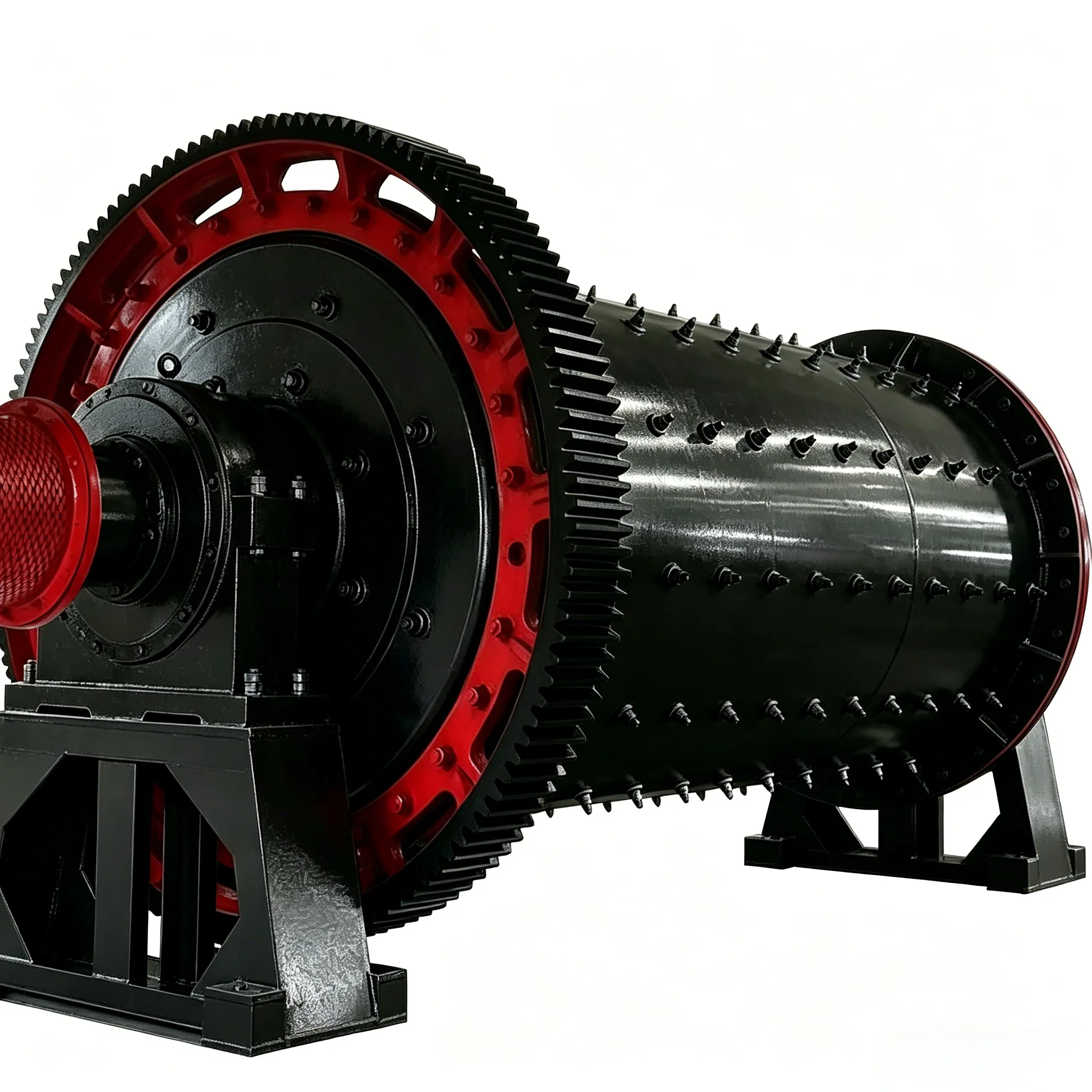
Clean the Kugelmühle shell interior: Remove accumulated dust, residual material, and oil from the inner wall, especially the annular groove area where the diaphragm will be installed. Ensure the surface is flat and free of protrusions.
Check shell roundness and diameter: Measure the actual inner diameter of the shell at the installation position. The ovality should be within the allowable range (generally ≤0.5% of D). If severe deformation is found, re‑rounding is required.
Inspect and prepare the mounting groove: If the mill originally has a pre‑embedded groove, check its width, depth, and position to match the diaphragm thickness. If not, machine a circular locating groove on‑site according to the drawings.
Pre‑fabricate diaphragm segments: Divide the complete diaphragm into several small segments (usually 2–4 pieces) according to the manhole size. Dry‑assemble them on a flat surface to check seam alignment and bolt hole positions, and mark them for reference.
Prepare fasteners and welding materials: Have ready high‑strength bolts, lock washers, sealing gaskets (e.g., asbestos or heat‑resistant rubber), and welding electrodes (if welding is required for fixation).
II. Installation Steps
Lift in the diaphragm segments: Insert each segment through the manhole into the mill. Take care to protect the slots from damage or deformation.
Initial positioning into the groove: Place the first segment into the annular groove of the shell. Use locating stops or temporary supports on the shell to hold it roughly in position. The clearance between the outer edge of the diaphragm and the shell inner wall should be uniform (typically 5–10 mm for thermal expansion, as mentioned earlier, with the diaphragm diameter made about 10 mm smaller).
Install the remaining segments: Insert the other segments into the groove sequentially, aligning the joints between adjacent segments. Ensure the slot directions are consistent and that the slots are staggered (as required) to maintain screening effectiveness.
Mount the central circular plate (or centre support): Connect the inner ends of all segments with the central circular plate and tighten with bolts. Ensure the ventilation holes in the central plate remain open and unblocked.
Tighten the shell fixing bolts: Using a torque wrench, symmetrically and gradually tighten the bolts that secure the outer edge of the diaphragm to the shell, following the design torque (typically 400–600 N·m, depending on bolt size). Pre‑tighten first, then apply force in 2–3 incremental stages to avoid eccentric loading.
Weld the segment joints (if required by design): For joints between segments, some designs call for welding reinforcement. Use intermittent (skip) welding, with each weld length about 50–80 mm and spacing 100–150 mm, to minimise thermal distortion. Wichtig: As emphasised earlier, welding between the diaphragm and the shell, or between the diaphragm and the liners, is generally avoided; only bolted connections should be used to prevent heat‑induced deformation.
Check slot dimensions and clearance: After installation, use a feeler gauge or special measuring tool to spot‑check slot widths (should be within ±0.5 mm of the design value, typically 5 mm). Remove any welding slag or metal burrs from the slots.
Install lifting scoops or guide cone (for double‑layer diaphragms): For double‑layer diaphragms, install the lifting vanes and the material‑guide cone between the two plates, adjusting their angles according to the drawings to ensure proper lifting and guidance of the material.
Final tightening and anti‑loosening treatment: Re‑tighten all bolts comprehensively, then lock them using double nuts or lock washers. Apply high‑temperature anti‑seize compound on the exposed threads.
III. Installation Quality Requirements (Acceptance Criteria)
Positional accuracy:
Perpendicularity deviation between the diaphragm centreline and the mill shell axis ≤1 mm/m (over the full length).
Axial positioning error of the diaphragm along the shell ≤±2 mm.
Radial clearance:
The gap between the diaphragm outer edge and the shell inner wall should be uniform, with the difference between maximum and minimum values ≤3 mm.
Fill the gap with heat‑resistant sealing material (e.g., asbestos rope) to prevent grinding media or material from leaking through.
Slot quality:
Slot widths should be consistent, with deviations ≤±0.5 mm from the design value.
Slots must be free of blockage, burrs, or obvious deformation; all slots should be fully open.
Fastening quality:
Pre‑torque deviation for all fixing bolts ≤±5%, with no signs of loosening.
Bolt heads should fully seat into the liner countersinks without tipping or tilting.
Welding quality (if applicable):
Welds should be uniform and sound, free from cracks, porosity, slag inclusions, or other defects.
The heat‑affected zone should show no significant discoloration (avoid overheating), and welding distortion ≤1 mm.
Overall rigidity:
Tapping various parts of the diaphragm with a light hammer should produce a clear, consistent sound—no hollow sounds, indicating secure and rigid installation.
Ventilation area:
The actual effective ventilation area of the diaphragm should be ≥95% of the design value, and all vent holes (central plate holes) should be unobstructed.
IV. Post‑installation Inspection and Trial Run
After installation, run the mill no‑load for 2–4 hours, listening for abnormal noises at the diaphragm and checking for bolt loosening or dust leakage.
After 8 hours of load operation, stop the mill and re‑check bolt tightness; perform hot‑retightening if necessary (since thermal expansion may reduce preload).
After 24 hours of operation, re‑measure slot widths and check for diaphragm distortion. If any abnormalities are found, adjust or replace components promptly.