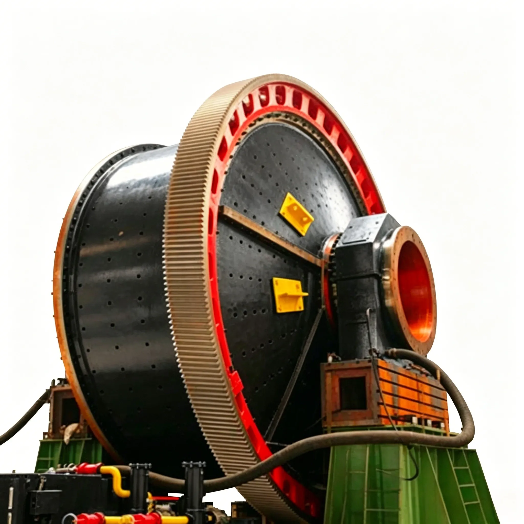
Mulino autogeno
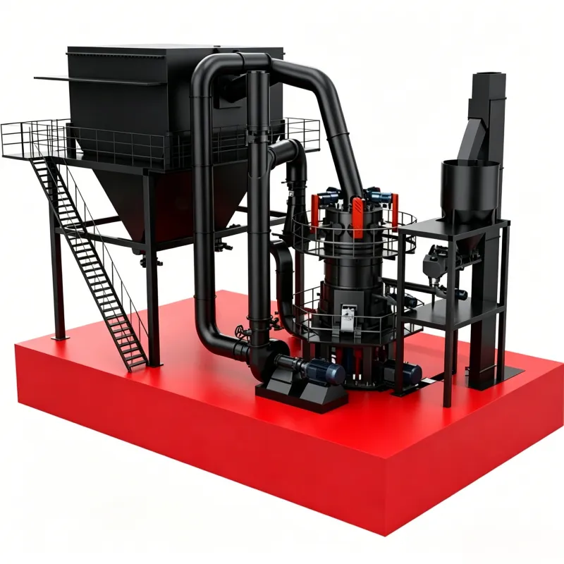
Principio di funzionamento di un mulino autogeno Il processo di macinazione di un mulino autogeno…

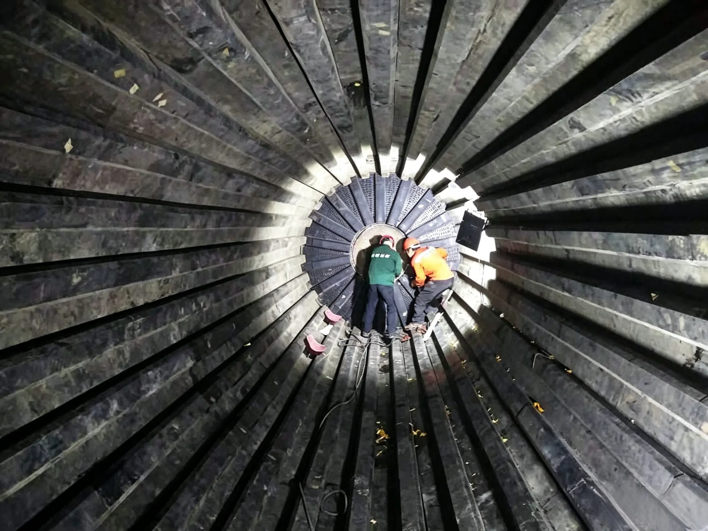
Due to the fine particle size and the characteristics of slag being easily crushed but difficult to grind, the movement pattern of the grinding media in a slag tube mill should primarily be based on grinding, rather than being lifted to impact the material as in a clinker ball mill. Therefore, the first compartment of a slag tube mill is preferably equipped with flat liners or grooved liners without steps. This can reduce the lifting height of the grinding media, lower power consumption, and at the same time increase the sliding between the grinding media and the liners, thereby enhancing the grinding capacity. In addition, since flat liners do not have the sharp-edged internal grooves found in step liners, they are less prone to material build-up when the slag has high moisture content, thus reducing the phenomenon of paste coating and plugging in the first compartment of the slag tube mill.
For the second and third compartments of the slag tube mill, small-wave liners or flat liners may be used.
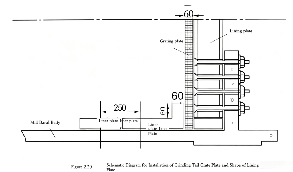
To prevent the grinding media from migrating between compartments, the liners on both sides of the partition diaphragms should be made into a special L-shape, as shown in Figure 2.19. The liners in the last ring adjacent to the discharge grate plate at the mill end should also adopt a similar special L-shaped configuration, as shown in Figure 2.20. The two partition diaphragms and the discharge grate plate inside the mill are to be manufactured by the cement plant itself, with a thickness of 60 mm. The lifting plates used for discharge at the mill end can be supplied by the equipment manufacturer, with their structure and dimensions remaining unchanged. The length of the last L-shaped liner at the mill end is related to the overall length of the mill, and its dimensions should be specially ordered.

Figure 2.19 Schematic diagram of the installation of the partition diaphragm and the shape of the liners.
When installing the partition diaphragm, an annular groove is left at the installation position of the diaphragm. The pre‑welded small pieces of the diaphragm are embedded into the groove and then welded together to form a complete diaphragm panel. To prevent thermal deformation of the diaphragm, welding between the diaphragm and the liners should be avoided.

 English English
 Spanish
 Russian
 Arabic
 Swahili
 French
 Turkish
 Portuguese
 Korean
 Japanese
 German
 Italian