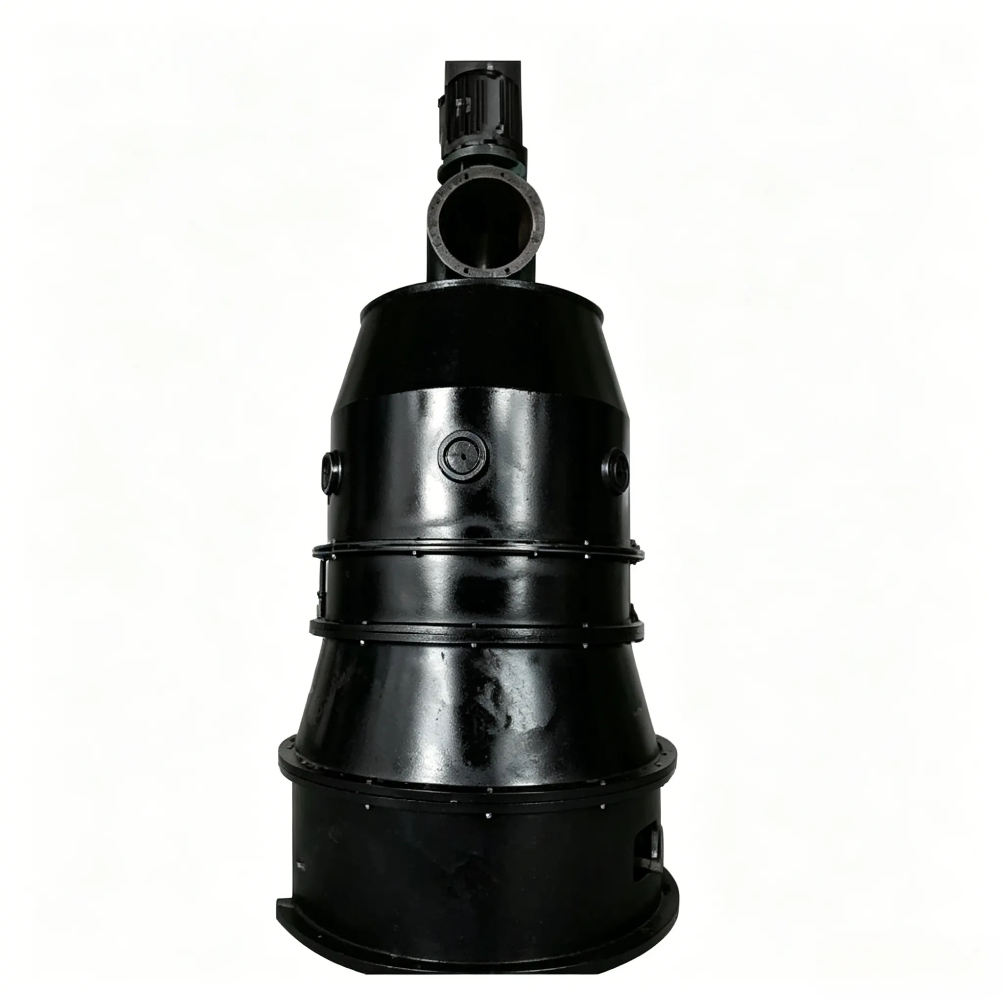
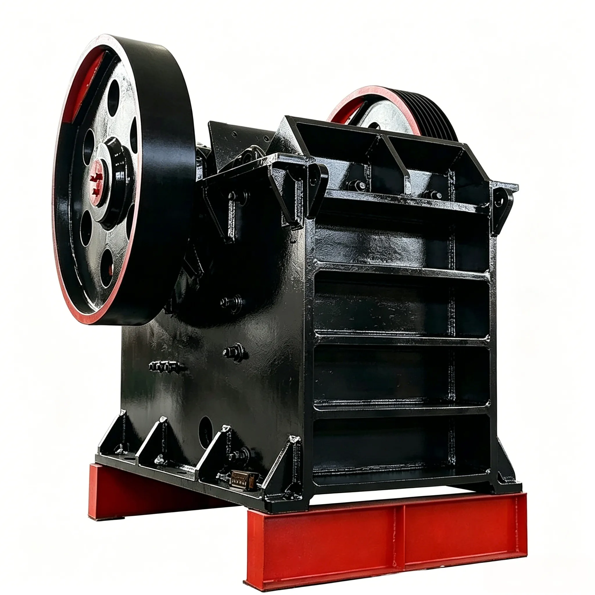
Frantoio a urto guidato SUM
Frantoio a urto con guida SUM Il frantoio della serie SUM è un frantoio a urto a secco con guida a ciclone…


(1) Reduce the feed particle size. When the feed particle size is decreased, the average ball diameter can be correspondingly reduced, and the grinding media filling rate can also be lowered, so the liner wear naturally decreases accordingly.
(2) Achieve uniform feeding, especially preventing the mill from running empty or with insufficient material.
(3) Adopt closed‑circuit grinding. Because the material‑to‑ball ratio in a closed‑circuit mill is high, the liner wear rate decreases correspondingly.
(4) Control the moisture content of the feed material below 2% to prevent acidic or alkaline substances in the material from forming corrosive compounds under high temperature and excessive moisture, which would accelerate liner wear.
(5) Strengthen internal ventilation to reduce the mill temperature and alleviate plastic deformation of the liners at high temperatures.
(6) Lower the feed material temperature – the temperature of the clinker entering the mill should be controlled below 50°C.
(7) Use grinding aids to improve the grindability of the material and reduce the wear effect.
(8) Improve the liner profile design:
① In a conventional mill, the thickness of a single liner is uniform, but during operation a very small area of the liner may wear quickly. Once the remaining thickness at that location is reduced to the allowable minimum, the entire liner must be replaced even though most of it is still intact. Improvement: appropriately increase the thickness of the areas that wear more quickly. For example, for the mill head liner, the thickness of the fast‑wearing areas should be 15–30 mm greater than other parts. To achieve this, the head liner of a tube mill with a diameter of 2–3 m can be designed in two rings, and for diameters over 3 m, in three rings. By dividing into rings, the fast‑wearing areas are concentrated in one ring, and the thickness of that ring can be increased to extend the replacement cycle and reduce wear. When designing such ring divisions, attention should also be paid to: the size and weight of each individual liner should not be too large for easy handling through the manhole; and the bolt holes on the liner and the end cover should be evenly distributed. The same approach can be applied to intermediate diaphragms and discharge grate plates by appropriately increasing the thickness of their worn areas.
② In the past, stepped liners in China were mostly designed as long strips with two bolt holes, with a thin edge thickness of 18–22 mm and a thick edge thickness of 70–90 mm. They were prone to cracking during use, and even more so when made of materials with high hardness and low toughness. Abroad, such liners are often designed as small square blocks with a single bolt hole, with a thin edge thickness of 55 mm and a thick edge thickness of 135 mm. Because of the greater thickness and the large difference between thin and thick edges, not only is the ball‑lifting effect stronger, but the overall structural strength is also higher, so even when made of high‑chromium cast iron, they are not prone to cracking.
③ Professor Qi Jiyu changed the liner arrangement of the DTM‑287/410 coal mill from 12 pieces per ring (30° each) to 18 pieces per ring (20° each). As a result, not only was the liner weight reduced by 35.9% (facilitating installation), but the maximum stress was also reduced by 41.8%, significantly improving durability.
④ When using high‑chromium white cast iron to manufacture tube mill liners, the liner blocks should be small in size, the structure should be simple, and the countersunk holes of the profiled liners should be changed to an elliptical shape.

 English English
 Spanish
 Russian
 Arabic
 Swahili
 French
 Turkish
 Portuguese
 Korean
 Japanese
 German
 Italian