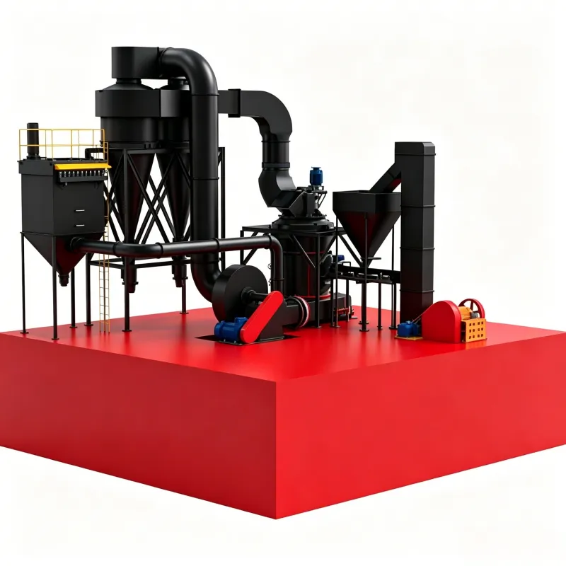
Mulino Raymond di grandi dimensioni
Introduzione al mulino Raymond di grandi dimensioni Il mulino Raymond di grandi dimensioni KX è un…


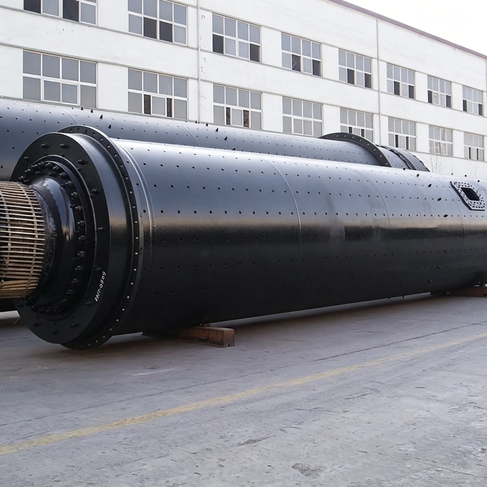
The liners of a ball mill are usually fixed to the inner surface of the shell with bolts, but in the fine grinding compartment they may also be installed in a brick‑laid (interlocking) manner. For brick‑laid liners, generally speaking, they are rarely disassembled unless they are worn out and need replacement. This creates considerable inconvenience when the mill discharge grate plate needs to be replaced, especially in cases where the fine grinding compartment liners are still in good condition and do not need replacement, but the discharge grate plate is severely worn and must be replaced. Because to replace the discharge grate plate, the fine grinding compartment liners must first be removed, and removing them brings about three problems: first, the brick‑laid liners, after long‑term impact and pressing by the grinding media and material inside the mill, undergo both thermal expansion and cold deformation, resulting in many “interlocking edges” between liners, making disassembly laborious; second, the removed liners, having deformed to different degrees, form “individual fits” between adjacent liners, making re‑installation difficult or even impossible; third, because the liners are brick‑laid, disassembly must start from the beginning (at the mill diaphragm) and go all the way to the end, requiring the entire set of liners to be removed, which involves a large amount of dismantling and reassembly work, extends downtime, and affects the equipment availability.
To address this difficulty, Shen Dongping developed a simple method to replace the discharge grate plate without dismantling the brick‑laid liners. Taking a φ2.2 m mill as an example, the procedure is described in detail below.
(1) Situation Analysis
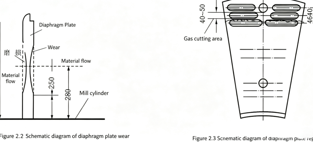
① The discharge grate plate, the diaphragm, and the mill head liners inside the mill have different degrees of wear at different diameters; as shown in Figure 2.2, wear is less at the end near the mill shell.
② The discharge grate plate is installed at the mill discharge end of the fine grinding compartment. The axial impact force from the grinding media is not large, and the back of the discharge grate plate is supported by the lifter bars, so the bending moment on the discharge grate plate is negligible.
③ The discharge grate plate is mostly made of ZGMn13, a low‑strength ordinary steel with good weldability. After welding, the performance of the weld zone metal is not inferior to that of the base metal.
(2) Operating Procedure
Each discharge grate plate has two fixing bolts. At a location about 40–50 mm from the bolt near the inner wall of the shell toward the centre of rotation of the shell, use gas cutting to cut the grate plate open (Figure 2.3). Remove the old grate plate, then use the removed old grate plate as a template to lay out the pattern on a new grate plate. Use gas cutting to cut the new grate plate to size, prepare a small bevel, and select suitable welding electrodes and welding machine current for welding.
(3) Benefits
Using this method to replace a set of discharge grate plates for a φ2.2 m × 6.5 m mill required only 10 hours for three workers, saving labor, time, and effort. It also avoided the trouble of being unable to reinstall the fine-compartment liners after they had been removed. The discharge grate plates replaced by this method have been in safe operation for several years with good results.
(4) Precautions
Since the new grate plates are cut using the old ones as templates, and the cutting positions on each old grate plate may vary, it is essential to maintain a one-to-one correspondence between the old and new grate plates. During installation, attention must be paid to the individual fitting of each grate plate.
 English English
 Spanish
 Russian
 Arabic
 Swahili
 French
 Turkish
 Portuguese
 Korean
 Japanese
 German
 Italian