
Hydrocyclone
Hydrocyclone The hydrocyclone is a device that uses centrifugal force to classify…
3.5.1.1 Installation of the Lower Frame
During assembly, first install the lower frame on the foundation, ensuring that its centerline coincides with the foundation centerline. When leveling, place a level 1 and a straightedge 2 on the machined surface at the upper end of the central bore inside the lower frame (see Figure 3-9). The permissible levelness deviation is 0.1 mm per meter. A gap greater than 30 mm shall be retained between the lower frame base and the foundation to allow for secondary grouting. After the grout layer has set, retighten the foundation bolts.
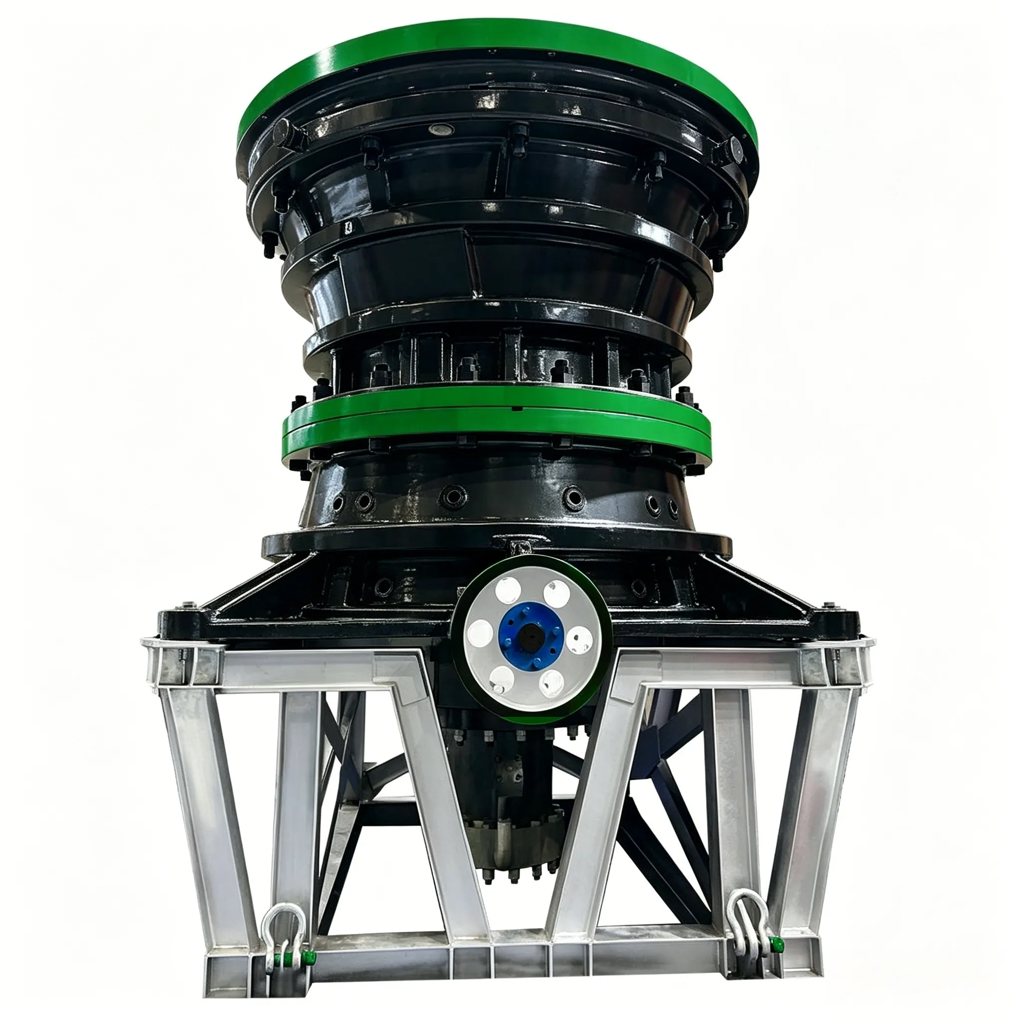
3.5.1.2 Installation of the Drive Unit
When installing the drive shaft, see Figure 3-10, care must be taken that the centers of the two bronze bushes 7 are on the same horizontal line. The radial clearance between the bronze bushes 7 and the shaft 3 shall be within the range of 2.5D/1000 to 3D/1000 mm (where D is the diameter of the shaft).

Figure 3-9 Leveling of the lower frame
1—Level; 2—Straightedge; 3—Frame base
When fixing the retaining ring 4, the axial play of the drive shaft shall be maintained within the range of 0.3–0.8 mm. A certain clearance, generally about 30 mm, shall be left between the outer independent bearing and the foundation to allow for secondary grouting.

Figure 3-10 Drive unit
1—Bearing; 2—Pulley; 3—Drive shaft; 4—Retaining ring; 5—Drive housing; 6—Jack screw; 7—Bronze bush; 8—Template; 9—Frame; 10—Adjusting shim
When installing the drive shaft 3, add an appropriate number of adjusting shims 10 between the flange of the drive housing 5 and the frame 9 to adjust the position of the bevel gear. Use a template 8 to check that the difference between l and a meets the product design requirements. If the drive housing 5 needs to be removed from the frame 9, this can be achieved by turning the three jack screws 6 on the drive housing.
3.5.1.3 Installation of the Eccentric Bushing Assembly
Before installing the eccentric bushing assembly, place the adjusting shims 3 onto the central sleeve 4 of the frame. The three thrust discs 2 between the central sleeve and the large bevel gear shall also be fixed to the central sleeve 4 and the large bevel gear 1 respectively using pin-screws (see Figure 3-11), and clean dirt from the discs and oil grooves.
During installation, special care shall be taken to protect the friction surfaces of the Babbitt metal layer to prevent damage and contamination. As shown in Figure 3-12, with the large end faces of the teeth aligned, check whether the tooth tip clearance after installation meets the requirements (measured at the outer end of the teeth); generally it should be 0.2m (where m is the module). If the clearance is too large or too small, adjust it by changing the number of adjusting shims.
The top of the tapered key used to secure the large bevel gear shall not be higher than the top end face of the eccentric bushing.

Figure 3-11 Schematic diagram of eccentric bushing adjustment
1—Bevel gear; 2—Thrust disc; 3—Adjusting shim; 4—Central sleeve

Figure 3-12 Meshing of the drive gears
Installation of the Middle Frame
When installing the middle frame, alignment must be performed based on the upper flange of the lower frame. The gaps between the flanges at all tapered contact surfaces shall be uniform around the circumference, with a permissible deviation of not more than 0.5 mm. The gap between the upper and lower mating surfaces is generally about 15 mm.
The number and thickness of metal shims used during liner installation may be adjusted according to actual conditions. When assembling the liners of the middle frame, the following requirements shall be met: The liners shall be assembled before the middle frame is lifted into place. After assembly, the space behind the liners shall be filled with a 1:3 cement mortar mix.
During installation, the dowel pins must be driven tight. After the machine has been operated under load for a period of time, drive each dowel pin tight again one by one to ensure that all pins around the circumference are uniformly stressed.
3.5.1.5 Installation of the Crushing Cone Assembly and the Spider
The installation procedure is as follows:
(1) Separate installation of the crushing cone. Use the lifting ring on the shaft to hoist the crushing cone into the frame. Then place wooden blocks on the ribs at the lower part of the frame to support the cone and ensure the proper height. At the same time, use wooden wedges inside the middle frame to wedge the movable cone firmly so that it is centered. After that, install the spider, fit the nut and outer sleeve onto the upper end of the main shaft, and finally install the cap. Then remove the wooden blocks and wedges.

Figure 3-13 Schematic diagram of special pit
1—Lifting ring; 2—Spider; 3—Crushing cone; 4—Pit
(2) Installation of the crushing cone together with the spider. This involves pre-assembling the spider and the crushing cone in a special pit, as shown in Figure 3-13 (this pit is also used when repairing the spider and the crushing cone). The complete assembly is then installed into the frame. When lifting the crushing cone and spider assembly, the steel rope must be attached to the arms of the spider. Under no circumstances shall the lifting ring at the upper end of the main shaft be used for lifting, as it may not be able to bear the load and cause an accident. If the crane capacity permits, this method is preferable for installation.
The crushing mantle of the crushing cone must be tightened with a nut to prevent loosening. Before tightening, to prevent rust and difficulty during disassembly, the space below the retaining ring (pressure plate) and the mating bolts shall be thoroughly coated with grease.
When assembling the spider with the middle frame, the spider arms shall be oriented in the direction of the feed chute to ensure that ore falls evenly into the crusher. The gap between the flange end faces of the spider and the middle frame shall be uniform around the circumference, with a permissible deviation of not more than 0.5 mm. After the assembly is verified to be acceptable, it shall be immediately secured with dowel pins.
3.5.1.6 Permissible installation deviations and inspection methods for gyratory crusher
The permissible installation deviations and inspection methods for the gyratory crusher shall comply with the requirements specified in Table 3-5.
Table 3-5 Permissible installation deviations and inspection methods for gyratory crusher (Table content not provided in the original text)
| Item No. | Item | Permissible Deviation | Unit | Inspection Method |
|---|---|---|---|---|
| 1 | Longitudinal and transverse centerline | 3.0 | mm | Check with steel rule |
| 2 | Elevation | ±5.0 | mm | Check with steel rule |
| 3 | Longitudinal and transverse levelness | 0.1/1000 | – | Check with straightedge and level |
| 4 | Coupling coaxiality | Shall comply with the requirements of GB 50231 | – | Check with feeler gauge or dial indicator |


