

Figure 9-5 shows a φ2700mm×3600mm overflow ball mill. The shell (1) is supported on the main bearings (7) by means of the end covers (3). The interior of the shell and end covers is lined with high‑manganese steel liners (4). Steel balls or cast iron balls of various sizes (φ25–150mm) are loaded into the shell in a prescribed proportion.
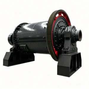
Figure 9-5 shows a φ2700mm×3600mm overflow ball mill. The shell (1) is supported on the main bearings (7) by means of the end covers (3). The interior of the shell and end covers is lined with high‑manganese steel liners (4). Steel balls or cast iron balls of various sizes (φ25–150mm) are loaded into the shell in a prescribed proportion. The motor (8) drives a pinion mounted on the transmission shaft, which in turn drives the large gear (11) on the shell, causing the mill to rotate.

Figure 9-5 φ2700mm×3600mm overflow ball mill
1 – shell; 2 – flange; 3 – end cover; 4 – liner; 5 – feed pipe; 6 – feeder; 7 – main bearing; 8 – electric motor; 9 – discharge pipe; 10 – retaining ring; 11 – large gear
Material enters the mill through the feeder (6) and the feed pipe (5). When the slurry level inside the shell rises above the lowest generatrix of the inner diameter of the discharge pipe (9), the ground material can be discharged from the mill together with water through the discharge pipe. The main components are described as follows:
(1) Mill shell. The shell of the mill is fabricated by welding steel plates. Flanges (2) for fixing the end covers are welded to both ends of the shell. One or two manholes are provided on the shell for installing shell liners, performing maintenance, and removing the grinding media.
(2) Mill end covers. Both end covers are equipped with hollow trunnions. For large mills, the end covers are made of cast steel; for small mills, cast iron may be used.
When assembling the end covers with the shell, only white lead is allowed on the mating surfaces – no gaskets of any kind are permitted. The bolts around the circumference are uniformly tightened. This ensures a tight connection while also facilitating disassembly.
To prevent wear of the end covers, in addition to fitting end cover liners made of high‑manganese steel on the inner surfaces, cast iron feed and discharge pipes (5 and 9) are installed inside the hollow trunnions. The fits between the hollow trunnions and the feed/discharge pipes must be tight, and necessary seals shall be provided.
The end of the discharge pipe (9) inside the hollow trunnion on the discharge end is made in a bell‑mouth shape (funnel shape). In addition, an annular retaining ring (10) is usually fitted at the root of the hollow trunnion to prevent slurry leaking through the end cover bolt holes from entering the bearing. Spiral ribs are cast into the discharge pipe (9), with the helix direction opposite to the mill rotation, thereby preventing steel balls and coarse material from being discharged with the slurry.
(3) Main bearing. The structure of the main bearing for wet grinding is shown in Figure 9‑6. The main bearing of the mill basically consists of the bearing base plate (1) inside the lower bearing housing, the spherical‑seat base (2), the self‑aligning spherical bearing bush (4) (with bearing lining cast inside), and the bearing cover (5). All parts of the above main bearing are made of cast iron except the bearing lining, which is cast with Babbitt metal.

Figure 9‑6 Main bearing of a wet grinding mill
1 – bearing base plate; 2 – spherical‑seat base; 3 – locating pin; 4 – spherical bearing bush; 5 – bearing cover; 6 – screw
Due to the large distance between the two bearings of the mill, and the inevitable manufacturing and assembly errors, it is difficult to ensure perfect concentricity. Under heavy load, deflection (sagging) is likely to occur. To avoid problems caused by the above factors, the bearing structure adopts a self‑aligning spherical bearing bush with good adjustability, so that the load acting on the pressure surfaces is uniformly distributed.
To prevent excessive movement of the spherical bearing bush during mill operation, a cylindrical locating pin (3) is installed between the spherical‑seat base (2) and the spherical bearing bush (4). To facilitate alignment during bearing installation, the position of the spherical‑seat base (2) can be adjusted using the screw (6). In the past, wedge adjustments were also used.
Timely lubrication must be ensured between the trunnion and the bearing lining. There are many lubrication methods, generally including central circulating oil lubrication, drip oil lubrication using oil cups, or wick lubrication.
Recently, double‑row roller bearings have been used in some mills instead of sliding bearings. They offer higher transmission efficiency and simplify auxiliary lubrication equipment and maintenance, but their manufacturing cost is very high.
(4) Mill transmission device. It consists of a large gear ring, a pinion, a transmission shaft, and an elastic coupling. The mill shell is rotated by the electric motor through the coupling and the gear transmission. The gear transmission comprises the gear ring mounted on the discharge end of the shell and the transmission gear. The transmission gear is mounted on the transmission shaft, which is supported on two double‑row concentric rolling bearings in bearing housings. The gears are completely enclosed by a dust cover.
For mills with a shell diameter less than 2100 mm or motor power below 400 kW, a Y‑series or JR‑type asynchronous motor with high starting torque is used, driving through a primary reducer and couplings. For larger ball mills or those with motor power exceeding 400 kW, a dedicated TDMK low‑speed synchronous motor is used, connected to the pinion via an air clutch, achieving single‑stage reduction to drive the shell.
Large mills are equipped with a slow‑speed auxiliary drive to rotate the shell at 0.1 r/min for barring (inching) purposes.
(5) Mill liners. Mill liners protect the main components of the mill from wear. The liners inside the shell also serve to lift the grinding media (balls, rods). To improve mill availability and productivity, continuous improvements are made to liner materials, fixing methods, structure, and size.
One of the main requirements for mill liners is wear resistance. Liner materials can include hard steel, high‑manganese steel, chromium steel, alloy cast iron, rubber, and magnetic liners. High‑manganese steel has sufficient impact toughness and undergoes surface work‑hardening upon impact, becoming hard and wear‑resistant. Therefore, it is widely used for liners. However, high‑manganese steel requires high processing technology and is relatively expensive. For fine grinding where the grinding action is mainly attrition and impact resistance is less critical, other cheaper wear‑resistant alloy cast irons may be chosen. Chromium‑added high‑manganese steel liners and chromium‑manganese‑silicon steel liners, which began to be used in the 1980s, perform even better than conventional high‑manganese steel liners. The disadvantages of metal liners are that they are difficult to shape, heavy, and inconvenient to install and remove.
Since 1990, rubber liners have been promoted in China. They offer good wear resistance, low weight, low noise, low ball consumption, ease of shaping, convenient installation and removal, and long service life.
The geometry and arrangement of liners directly affect mill efficiency. Therefore, as shown in Figure 9‑7, several liner shapes are available to suit different conditions. Generally, they can be divided into smooth and non‑smooth (profiled) liners. Smooth liners allow greater ball sliding and stronger attrition, making them suitable for fine grinding. Non‑smooth liners lift balls to a higher point of fall, providing greater impact force and stronger agitation of balls and ore, making them suitable for coarse grinding. Among these, the long‑strip liners developed in China have the advantages of simple fabrication, few or no screws for fixing (they are clamped by end‑cover liners or wedge bars), easy installation, reduced slurry leakage through bolt holes, and improved shell strength. In addition, angular spiral liners have also been developed and adopted in China.

Figure 9‑7 Shapes of various liners
a – wedge shape; b – wave shape; c – flat‑convex shape; d – flat shape; e – stepped shape; f – long‑strip shape; g – ship rudder shape; h – K‑shaped rubber liner; i – B‑shaped rubber liner
The rubber liners manufactured in China are generally of an approximately rectangular, flat‑convex shape. When assembled with shell lifter bars (i.e., lifter liners), they usually become K‑shaped or B‑shaped. Since the 1980s, these rubber liners have been widely adopted in many mines and plants, with very good results.
Metal liners typically have a thickness of 50–150 mm, while rubber liners are generally 40–80 mm thick. The service life of metal liners is usually about six months to one year, whereas rubber liners can last up to about three years.
In recent years, magnetic liners have developed rapidly, with continuously improving performance, and are being steadily promoted and applied. Ball mill magnetic liners are made by wrapping permanent magnetic materials with rubber or steel, and are therefore classified into two types: metal magnetic liners and rubber magnetic liners. Currently, the former (metal magnetic liners) are more widely used. Magnetic liners can use magnetic force to adsorb a layer of ferromagnetic material on their surface, so that the material and grinding media do not directly contact the liner surface during operation, thereby reducing liner wear. At the same time, they can also be adsorbed onto the mill shell wall without the need for bolts. Because magnetic liners are lighter and thinner than manganese steel liners, they also offer energy savings and increased production capacity.
The general characteristics of magnetic liners are:
Because the feed to primary ball mills is coarse, impact forces are high, and wear is severe, magnetic liners are generally suitable only for secondary ball mills. The technical parameters of metal magnetic liners are listed in Table 9‑2.
Table 9‑2 Technical parameters of metal magnetic liners
| Serial No. | Ball mill specifications / mm×mm | Magnetic liner model | Estimated weight of shell liner / kg | Estimated weight of end cover liner / kg | Total estimated weight / kg |
|---|---|---|---|---|---|
| 1 | MQY900×1800 | GSQ‑Ⅱ0.9 | 1500 | 400 | 1900 |
| 2 | MQY1200×2400 | GSQ‑Ⅱ1.2 | 2650 | 550 | 3200 |
| 3 | MQY1500×2000 | GSQ‑Ⅱ2.0 | 3300 | 810 | 4110 |
| 4 | MQY1500×2000 | GSQ‑Ⅱ1.5A | 4180 | 810 | 4990 |
| 5 | MQY2100×3000 | GSQ‑Ⅱ2.1 | 6250 | 1580 | 7830 |
| 6 | MQY2100×4500 | GSQ‑Ⅱ2.1 | 8820 | 1580 | 10400 |
| 7 | MQY2700×2100 | GSQ‑Ⅱ2.7A | 5860 | 2910 | 8870 |
| 8 | MQY2700×3600 | GSQ‑Ⅱ2.7A | 10050 | 2910 | 12980 |
| 9 | MQY2700×4000 | GSQ‑Ⅱ2.7A | 11070 | 2910 | 13980 |
| 10 | MQY3200×4500 | GSQ‑Ⅱ3.2A | 14444 | 3510 | 17945 |
| 11 | MQY3200×5400 | GSQ‑Ⅱ3.2A | 17332 | 3510 | 20842 |
| 12 | MQY3600×4500 | GSQ‑Ⅱ3.6A | 17973 | 4618 | 22591 |
| 13 | MQY3600×4500 | GSQ‑13.6H | 21112 | 4830 | 25942 |
| 14 | MQY3600×6000 | GSQ‑Ⅱ3.6A | 23964 | 4618 | 28582 |
| 15 | MQY3600×6000 | GSQ‑Ⅱ3.6H | 28149 | 4830 | 32979 |
(6) Mill feeder. The material inside the mill shell (including new feed and returned sand from classification) is fed into the mill entirely by the feeder. The feeder types include drum, worm (spiral), and combination feeders.
1) Drum feeder. This type of feeder can only be used when the feed position is higher than the mill axis level. It is generally used on open‑circuit (or dry) mills. Its structure is shown in Figure 9‑8. It consists of a conical drum (1) open at both ends, a cover (2), and a partition plate (3). These three parts are bolted together.

Figure 9‑8 Drum feeder
1 – drum; 2 – cover; 3 – partition plate
In Figure 9‑8, the drum (1) can be cast from cast iron or welded from steel plates. A spiral partition plate is provided inside the drum. The cover (2) is a truncated conical short sleeve, with a feed circular hole at the smaller end. The partition plate (3), made of steel plate, is located between the drum and the cover. The partition plate has a sector‑shaped hole that allows material to enter the spiral of the drum. The feeder is bolted to the feed trunnion of the mill shell.
When material is fed through the circular hole of the cover (2), it passes through the sector‑shaped hole in the partition plate (3) into the drum (1), and is then conveyed into the mill by the internal spiral partition plate of the drum. The feed material can have a particle size up to 70 mm. In dry mills, a spout feeder may also be used.
2) Worm feeder (Figure 9‑9). It is a spiral‑shaped scoop. To convey the scooped material into the mill, a circular hole is provided on the side wall along the rotational axis direction. The feeder is bolted onto the trunnion of the mill shell, so that the trunnion aligns with the hole of the feeder. The outer casing of the feeder is welded from steel plates. At the end of the feeder scoop, there is a replaceable scoop (2) cast from manganese steel or alloy cast iron. The inner surface of the feeder is lined with steel plates.
The characteristic of the worm feeder is its ability to scoop slurry from a level lower than the mill axis and feed it into the mill. Therefore, this type of feeder is suitable for closed‑circuit second‑stage grinding where the mill is combined with a classifier.

Figure 9‑9 Worm feeder
1 – scoop; 2 – scoop
3) Combined feeder (Figure 9‑10). This type of feeder can simultaneously feed both the new feed material and the classifier returns (sand) into the mill. The greatest advantage of the combined feeder is that coarse material can be fed directly into the mill without passing through the feed chute of the worm scoop. When the ball mill diameter exceeds 3200 mm, a double‑scoop combined feeder is used.

Figure 9‑10 Combined feeder
1 – drum; 2 – scoop; 3 – scoop; 4 – cover
In the past, the manufacturing and production of ball mills were organized according to product series. Nowadays, production is based on user requirements: whatever type and specifications the user needs, that is what is produced. Therefore, the model and specifications are not uniform across different manufacturers. The technical performance of wet overflow ball mills currently produced in China is shown in Table 9‑3. An example explaining the meaning of the model and specifications is as follows:

Table 9‑3 Technical performance of wet overflow ball mills
| Model | Shell size (D×L) / mm×mm | Effective shell volume / m³ | Ball charge / t | Operating speed / r·min⁻¹ | Motor power / kW | Discharge particle size / mm | Throughput / t·h⁻¹ | Reference weight / t | Remarks |
|---|---|---|---|---|---|---|---|---|---|
| MQY1513 | 1500×3000 | 4.0 | 8.4 | 27.6 | 75 | 0.8~0.074 | 11~2.6 | 15.1 | 380V |
| MQY1535 | 1500×3500 | 4.6 | 10 | 27.6 | 75~90 | 0.8~0.074 | 13.2~3.0 | 16.0 | 380V |
| MQY1830 | 1800×3000 | 6.5 | 12 | 25.3 | 110~132 | 0.8~0.074 | 20~4.5 | 27.8 | 380V |
| MQY1835 | 1800×3500 | 7.58 | 15 | 25.3 | 132~160 | 0.8~0.074 | 23~5.0 | 29.7 | 380V |
| MQY1840 | 1800×4000 | 8.65 | 16 | 25.3 | 160~185 | 0.8~0.074 | 25~6.0 | 32.6 | 380V |
| MQY1845 | 1800×4500 | 9.75 | 18 | 25.3 | 185~210 | 0.8~0.074 | 28~6.8 | 35.5 | 380V |
| MQY2122 | 2100×2200 | 6.7 | 14.7 | 23.8 | 160 | 0.8~0.074 | 22~5.0 | 42.9~46.5 | 380V |
| MQY2130 | 2100×3000 | 9.2 | 17 | 23.8 | 185 | 0.8~0.074 | 25~5.8 | 48.0 | 380V |
| MQY2136 | 2100×3600 | 11 | 19 | 23.8 | 210 | 0.8~0.074 | 28~6.0 | 49.9 | 380V |
| MQY2140 | 2100×4000 | 12.2 | 20.5 | 23.8 | 220 | 0.8~0.074 | 30~7.0 | 51.3 | 380V |
| MQY2145 | 2100×4500 | 13.8 | 22 | 23.8 | 250 | 0.8~0.074 | 34~8.0 | 54.0 | 380V |
| MQY2424 | 2400×2400 | 9.8 | 18.8 | 22.8 | 210 | 0.8~0.074 | 30~6.2 | 57.0 | 380V |
| MQY2430 | 2400×3000 | 12.2 | 23 | 22.8 | 250 | 0.8~0.074 | 34~6.6 | 59.68 | 380V |
| MQY2436 | 2400×3600 | 14.6 | 25 | 22.8 | 280 | 0.8~0.074 | 40.5~7.9 | 62.9 | 380V |
| MQY2440 | 2400×4000 | 16.2 | 28 | 22.8 | 315 | 0.8~0.074 | 45~8.7 | 65.5 | 380V |
| MQY2445 | 2400×4500 | 18.2 | 31 | 22.8 | 355 | 0.8~0.074 | 50~9.8 | 63.5 | 380V |
| MQY2721 | 2700×2100 | 10.7 | 20 | 21.7 | 280 | 3.0~0.074 | 76~6.0 | 66.7 | 6~10kV |
| MQY2727 | 2700×2700 | 13.8 | 25.5 | 21.7 | 315 | 3.0~0.074 | 98~7.8 | 75.6 | 6~10kV |
| MQY2730 | 2700×3000 | 15.3 | 28.0 | 21.7 | 355 | 3.0~0.074 | 108~8.8 | 81.8 | 6~10kV |
| MQY2736 | 2700×3600 | 18.4 | 34 | 21.7 | 355~400 | 3.0~0.074 | 130~10.5 | 83.5 | 6~10kV |
| MQY2740 | 2700×4000 | 20.5 | 37 | 21.7 | 400~450 | 3.0~0.074 | 144~11.5 | 87.6 | 6~10kV |
| MQY2745 | 2700×4500 | 23.0 | 42.5 | 21.7 | 500 | 3.0~0.074 | 180~13 | 127 | 6~10kV |
| MQY3231 | 3200×3100 | 22.65 | 22.65 | 18.6 | 450 | 3.0~0.074 | 164~14.4 | 131.0 | 6~10kV |
| MQY3236 | 3200×3600 | 26.20 | 26.2 | 18.8 | 500 | 3.0~0.074 | 171~17.1 | 135.0 | 6~10kV |
| MQY3240 | 3200×4000 | 29.2 | 29.2 | 18.6 | 560 | 3.0~0.074 | 190~20 | 139.0 | 6~10kV |
| MQY3245 | 3200×4500 | 32.8 | 61.00 | 18.6 | 630 | 3.0~0.074 | 228~22 | 148.7 | 6~10kV |
| MQY3254 | 3200×5400 | 39.3 | 73.0 | 18.6 | 710 | 3.0~0.074 | 270~20 | 165 | 6~10kV |
| MQY3640 | 3600×4000 | 35.6 | 67 | 17.3 | 710 | 3.0~0.074 | 210~20 | 170 | 6~10kV |
| MQY3645 | 3600×4500 | 40.8 | 76 | 17.3 | 800~1000 | 3.0~0.074 | 233~26 | 180 | 6~10kV |
| MQY3650 | 3600×5000 | 45.3 | 86 | 17.3 | 1120 | 3.0~0.074 | 260~31.5 | 200 | 6~10kV |
| MQY3660 | 3600×6000 | 54.4 | 102 | 17.3 | 1250 | 3.0~0.074 | 280~34 | 240 | 6~10kV |
| MQY3685 | 3600×8500 | 79.0 | 131 | 17.3 | 1500 | 3.0~0.074 | 400~45 | 280 | 6~10kV |
| MQY4564 | 4500×6400 | 85 | 174 | 14.54 | 2000 | 3.0~0.074 | 158 | ||
| MQY4570 | 4500×7000 | 111 | 190 | 15.6 | 2500 | 3.0~0.074 | 350 | ||
| MQY5080 | 5030×8000 | 145 | 240 | 14.2 | 3500 | 3.0~0.074 | 250 | ||
| MQY6295 | 6200×9500 | 262 | 13.08 | 6000 | 3.0~0.074 |


