

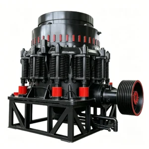
Cone crushers are known worldwide as “Symons type” crushers. Because they offer a large crushing ratio, high efficiency, low power consumption, uniform product size
Cone crushers are known worldwide as “Symons type” crushers. Because they offer a large crushing ratio, high efficiency, low power consumption, uniform product size, and suitability for crushing hard ores, they have been widely adopted in many countries since their introduction in 1920. They continue to be improved, including the incorporation of hydraulic devices, making them even more refined. The above characteristics of cone crushers reflect their structural features. Cone crushers have a rotational speed 2.5 times higher and a swing angle four times larger than those of gyratory crushers. In the crushing process with such high speed and large stroke, the ore in the crushing chamber is not squeezed by a movable cone moving slowly with a small stroke, as in a gyratory crusher, but is subjected to rapid impacts with a large stroke. This impact crushing method facilitates the comminution of ore, resulting in high crushing efficiency.
Due to the high speed and large stroke of cone crushers, the ore in the crushing chamber is in a sliding state along the cone surface for 95% of the time. That is, at any given moment, only 5% of the ore is being crushed. Because the ore is sliding downward for 95% of the time, the crusher has high throughput and thus high productivity. Since only 5% of the ore is being crushed, only 5% of the crushing chamber area is actually crushing ore, resulting in low power consumption. Moreover, the high pressure per unit area on the ore in the localized crushing area makes it suitable for crushing hard ores. Owing to its high rotational speed and the presence of a parallel zone of varying lengths at the lower part of the crushing chamber, the ore is crushed at least once within the parallel zone. Therefore, cone crushers produce a uniform product size.
Depending on the crushing operation requirements, cone crushers can be used for medium crushing and fine crushing. The difference between medium and fine crushing cone crushers lies in the shape and size of the crushing chamber. They are divided into three types, as shown in Figure 4-1.

Figure 4-1 Cross‑sectional views of crushing chambers
a – Standard type
b – Intermediate type (Medium type)
c – Short‑head type
Standard type – used for medium crushing of ores;
Intermediate type – used for medium and fine crushing of ores;
Short‑head type – used for fine crushing of ores.
Figure 4-1 and Table 4-1 list the feed opening (B), discharge opening (e), and parallel zone length (L) for the three different types of cone crushers. The generally recommended maximum feed size is 0.85 times the feed opening. The maximum product size depends on the hardness of the ore being crushed, the regularity of the mantel and concave liners, the crusher’s performance, and the rational configuration of related equipment. Under favourable conditions, the maximum product size may not exceed 1.5 times the discharge opening, with 70% of the product being smaller than the discharge opening. Under unfavourable conditions, the maximum product size can reach up to 4 times the discharge opening, and 80% of the product may be larger than the discharge opening.
Table 4‑1 Feed opening and discharge opening dimensions of cone crushers (mm)
| data | Standard | Intermediate | Short‑head | |||||||||||
| model | 600 | 900 | 1200 | 1750 | 2200 | 900 | 1200 | 1750 | 2200 | 600 | 900 | 1200 | 1750 | 2200 |
| inlet size B | 75 | 135 | 170 | 250 | 350 | 70 | 115 | 215 | 275 | 40 | 50 | 60 | 100 | 130 |
| outlet size e | 12~25 | 15-502 | 20-50 | 25~60 | 30~60 | 5-20 | 8~25 | 10-30 | 10~30 | 3~13 | 3~13 | 3~15 | 5-15 | 5-15 |
| parallel zoneL | 60 | 75 | 100 | 150 | 175 | 90 | 120 | 150 | 250 | 125 | 150 | 200 | 275 | 350 |
Depending on the method of discharge opening adjustment and overload protection, cone crushers can be divided into two types: spring protection and hydraulic protection. Hydraulic protection is further divided into single-cylinder hydraulic and multi-cylinder hydraulic types. The hydraulic protection type represents the development trend of cone crushers.
An example of the model specification interpretation for cone crushers is as follows:

Construction of a Spring Cone Crusher
The construction of a cone crusher is shown in Figure 4-2. It consists of a frame, transmission system, adjustment device, hydraulic system, lubrication system, and other components.
The motor directly drives the small bevel gear (7) on the drive shaft through an elastic coupling (5). The small bevel gear drives the eccentric bushing (12) to rotate inside the straight bushing (13) within the central sleeve of the frame via the large bevel gear. Inside the eccentric bushing (12) there is a tapered hole offset by about 2° from its axis of rotation. A tapered bushing (11) is fitted into this hole. The cone head (15) is supported by a bronze bowl-shaped spherical bearing (14). The lower tapered part of the main shaft (9) is inserted into the tapered bushing (11). Thus, when the eccentric bushing (12) rotates, the centerline of the main shaft (9) traces a conical surface in space, causing the movable cone (4) to perform a gyratory swing around the fixed point O. As a result, the surface of the movable cone liner (16) alternately approaches and moves away from the surface of the fixed cone liner (17).
The ore to be crushed falls from the feed box (19) onto the distributing plate (1) at the upper end of the movable cone, from where it is evenly distributed into the crushing chamber around the movable cone. At the moment the movable cone moves away from the fixed cone liner, the ore enters the crushing chamber. When the movable cone swings toward the fixed cone, the ore is crushed for the first time. When the movable cone moves away from the fixed cone again, the ore falls to the position where it will be crushed a second time. In this manner, the ore is crushed several times as it descends, and is finally discharged from the crusher.
The eccentric bushing (12) is supported on a thrust bearing (8) consisting of four disks. The lowermost copper disk is fixed to the bottom cover (10) of the frame. The uppermost steel disk is connected to the eccentric bushing with a pin, and both rotate together. The three sliding surfaces of the two middle disks (one steel and one copper) each slide relative to each other at approximately one‑third of the rotational speed of the eccentric bushing.

Figure 4‑2 Structure of a cone crusher
1 – Distributing plate 2 – Adjusting ring 3 – Support sleeve 4 – Movable cone 5 – Elastic coupling 6 – Drive shaft housing 7 – Small bevel gear 8 – Thrust bearing 9 – Main shaft coupling 10 – Frame bottom cover
11 – Tapered bushing 12 – Eccentric bushing 13 – Straight bushing 14 – Bowl-shaped spherical bearing 15 – Cone head (or mantle core) 16 – Movable cone liner (mantle) 17 – Fixed cone liner (concave)
18 – Spring 19 – Feed box
The upper part of the frame is equipped with a support sleeve (3), which is pressed tightly against the frame by the pressure of several sets of compression springs arranged around the periphery. The support sleeve has a (zigzag / buttress) internal thread, into which the adjusting ring (2) — which carries the fixed cone liner (17) — is screwed. Turning the adjusting ring to the left or right raises or lowers the fixed cone liner in the vertical direction, thereby adjusting the discharge opening.
The springs (18) around the frame serve both to generate the crushing force during normal operation and to act as a safety device protecting the crusher from damage. When an uncrushable object falls into the crusher, the crushing force increases sharply, causing the springs to compress further. This lifts one side of the upper part of the crusher (i.e., the support sleeve and adjusting ring), thereby increasing the gap between the fixed cone liner and the movable cone liner, allowing the uncrushable object to be discharged through the discharge opening. Afterwards, the support sleeve and adjusting ring return to their original position by the pressure of the springs.
The friction surfaces of the moving parts in a cone crusher are subjected to high pressures and relatively high speeds; therefore, lubrication is extremely important for cone crushers. Currently, all sizes of cone crushers use a central circulating thin‑oil lubrication system with an oil station. Low‑pressure oil supplied by the lubrication station enters the crusher in two paths. One path goes through the oil inlet hole in the bottom cover (10) of the frame to lubricate the thrust bearing (8), the straight bushing (13), the tapered bushing (11), and the bowl‑shaped spherical bearing (14). The large and small bevel gears are lubricated by the return oil from the tapered bushing and the bowl‑shaped spherical bearing. The other path goes through the oil inlet hole in the drive shaft housing (6) to lubricate the bearings at both ends of the drive shaft. After lubricating the various parts, the oil flows back to the oil station through the return pipe.
The commonly used lubricating oils at the oil station are: No. 20 or No. 30 machine oil in winter; No. 40 machine oil under normal temperatures; and No. 50 machine oil in summer.
During ore crushing, a large amount of dust is generated. To prevent dust from entering the interior of the crusher, a water‑seal dust prevention device is provided, as shown in Figure 4-3. The water‑seal dust prevention device consists of a water storage tank (1), a drain tank (2), a spherical ring (4), a baffle plate (5), and a dust seal ring (3). Dust‑prevention water is fed through the inlet pipe into the water storage tank (1). When the tank is full, water freely overflows into the drain tank (2) and is discharged from the crusher through the outlet pipe. Because the spherical ring (4) is immersed in the water storage tank (1), any dust that contacts the spherical ring is carried into the water and flows out with the overflowing water. Thus, dust cannot pass through the spherical ring and enter the crusher. The baffle plate (5) prevents water splashed up by the spherical ring (4) during crusher operation from getting into the bowl‑shaped bearing. The clearance between the dust seal ring (3) and the spherical ring (4) is generally kept at 2–4 mm. This clearance prevents large amounts of dust from entering the water storage tank, thereby reducing the load on the water‑seal device.

Figure 4-3 Water seal dust prevention device
1 – Water storage tank 2 – Drain tank 3 – Dust seal ring 4 – Spherical ring 5 – Baffle plate
Table 4‑2 Technical parameters of PYT type spring cone crushers
| Model / Specification | Feed opening (mm) | Max feed size (mm) | Discharge opening adjustment range (mm) | Capacity (t/h)① | Bottom diameter of crushing cone (mm) | Eccentric sleeve speed (r/min) | Motor power (kW) | Number of spring sets | Total spring pressure / pressure per set (t) | Lubrication station capacity (L/min) | Cooling water consumption (m³/h) | Mass (t)② |
|---|---|---|---|---|---|---|---|---|---|---|---|---|
| PYT‑B0607 | 75 | 65 | 12–25 | 40 | 600 | 355 | 30 | 8 | 40 / 5 | 16 | 1.2 | 5.2 |
| PYT‑D0604 | 40 | 36 | 3–13 | 12–23 | 600 | 355 | 30 | 8 | 40 / 5 | 16 | 1.2 | 5.2 |
| PYT‑B0913 | 135 | 115 | 15–50 | 50–90 | 900 | 333 | 55 / 60 | 10 | 70 / 7 | 16 | 1.2 | 10.2 |
| PYT‑Z0907 | 70 | 60 | 5–20 | 20–65 | 900 | 333 | 55 / 60 | 10 | 70 / 7 | 16 | 1.2 | 10.2 |
| PYT‑D0905 | 50 | 40 | 3–13 | 15–50 | 900 | 333 | 55 / 60 | 10 | 70 / 7 | 16 | 1.2 | 10.2 |
| PYT‑B1217 | 170 | 145 | 20–50 | 110–168 | 1200 | 300 | 110 | 10 | 150 / 15 | 63 | 3 | 23.6 |
| PYT‑Z1211 | 115 | 100 | 8–25 | 42–135 | 1200 | 300 | 110 | 10 | 150 / 15 | 63 | 3 | 23.4 |
| PYT‑D1206 | 60 | 50 | 3–15 | 18–105 | 1200 | 300 | 110 | 10 | 150 / 15 | 63 | 3 | 24.3 |
| PYT‑B1725 | 250 | 215 | 25–60 | 280–430 | 1750 | 245 | 155 | 12 | 300 / 25 | 125 | 6 | 50 |
| PYT‑Z1721 | 215 | 185 | 10–30 | 115–320 | 1750 | 245 | 155 | 12 | 300 / 25 | 125 | 6 | 50 |
| PYT‑D1710 | 100 | 85 | 5–15 | 75–230 | 1750 | 245 | 155 | 12 | 300 / 25 | 125 | 6 | 49 |
| PYT‑B2235 | 350 | 300 | 30–60 | 590–1000 | 2200 | 220 | 280 / 260 | 16 | 400 / 25 | 125 | 6 | 78.9 |
| PYT‑Z2227 | 275 | 230 | 10–30 | 200–580 | 2200 | 220 | 280 / 260 | 16 | 400 / 25 | 125 | 6 | 80.6 |
| PYT‑D2213 | 130 | 100 | 5–15 | 120–340 | 2200 | 220 | 280 / 260 | 16 | 400 / 25 | 125 | 6 | 80.5 |
Footnotes:
① Capacity is calculated based on a bulk density of the ore of 1.6 t/m³.
② Mass of the machine does not include the motor weight.
Construction of a Single-Cylinder Hydraulic Cone Crusher
The crushing action and crushing process of a single-cylinder hydraulic cone crusher are essentially the same as those of a spring cone crusher.
Figure 4-4 shows the structure of a single-cylinder hydraulic cone crusher. Compared with the spring cone crusher, the main features of this type of single-cylinder hydraulic cone crusher are the adoption of hydraulic adjustment, hydraulic protection, and hydraulic unloading (for removing blocked ore).

Figure 4‑4 Structure of a single‑cylinder hydraulic cone crusher
1 – Upper frame 2 – Crushing cone 3 – Eccentric sleeve 4 – Base 5 – Drive unit 6 – Adjusting shim
7 – Hydraulic cylinder
Apart from the differences necessitated by the hydraulic design — such as the hydraulic system, the replacement of the bowl‑shaped bearing with a thrust bearing at the lower end of the main shaft and a tapered sleeve support at the upper end, and the use of a sealing cylinder and sealing ring instead of the water seal dust prevention — other differences are: the crusher body rests on four rubber support pads and does not need to be fixed with foundation bolts; during operation, the entire crusher body can freely sway. In addition, V‑belt drive is used.
When the crushing chamber of a spring crusher becomes clogged or jammed by tramp iron, it usually takes one or two shifts to clear it. However, with this type of crusher, the problem can be solved simply by operating the hydraulic system. Because the crusher rests on four rubber pads, the machine sway caused by the inertial forces of the movable cone and eccentric sleeve during operation is absorbed by the rubber pads, thereby reducing the load on the foundation. As a result, large foundation bolts and a massive foundation are not required (only small bolts are needed to fix the foot pad trays to the foundation), thus lowering installation costs. This hydraulic design greatly improves the usability of the cone crusher. To adjust the discharge opening to a smaller size, oil is pumped from the hydraulic tank (4) under the piston of the hydraulic cylinder (2), raising the movable cone (1) to the desired position (see Figure 4‑5a). To increase the discharge opening, the oil under the piston of the hydraulic cylinder (2) is drained back to the hydraulic tank (4), allowing the movable cone (1) to lower to the desired position (Figure 4‑5b).

Figure 4‑5 Automatic adjustment of the discharge opening
a – Movable cone rises, discharge opening decreases
b – Movable cone lowers, discharge opening increases
1 – Movable cone 2 – Hydraulic cylinder 3 – Accumulator 4 – Oil tank
On the oil level indicator of the hydraulic oil tank, a discharge opening scale corresponding to the discharge opening size is provided. The difference in the discharge opening reading caused by a change in oil level indicates the amount of change in the discharge opening. During operation, the discharge opening can be adjusted at any time according to the required product size. Therefore, adjusting and controlling the discharge opening by changing the amount of oil under the hydraulic piston is both accurate and convenient.
The automatic protection and automatic unloading are described below.
(1) Automatic protection. First, nitrogen gas is charged into the accumulator (3) so that its pressure is higher than the oil pressure required for normal crushing. When a tramp iron piece or other uncrushable object enters the crushing chamber, the oil pressure in the high‑pressure oil circuit becomes greater than the nitrogen pressure inside the accumulator. The piston of the accumulator (3) then compresses the nitrogen, allowing hydraulic oil to enter the accumulator. As a result, the piston in the hydraulic cylinder (2) lowers, and the movable cone lowers with it. At this point, the discharge opening increases, and the tramp iron or other uncrushable object is discharged from the crusher, thus providing protection (see Figure 4‑6).
(2) Automatic unloading. When the crusher stops unexpectedly during normal feeding due to a malfunction or power failure, the crushing chamber becomes blocked with ore. However, a cone crusher is not allowed to start under load, so unloading is required.
To remove the blocked ore, the principle of hydraulic discharge opening adjustment can be used. When a blockage occurs in the crushing chamber, the hydraulic system can be operated to raise and lower the movable cone repeatedly, thereby crushing the blocked ore and discharging it from the crusher. This greatly reduces the difficulty of manual removal.
This type of crusher not only has the excellent performance characteristics described above, but also has a simple structure. As a result, it not only saves maintenance and adjustment workload and increases equipment utilization, but also eliminates the need for a large foundation and greatly reduces manufacturing workload.

Figure 4‑6 Automatic protection principle
1 – Movable cone 2 – Hydraulic cylinder 3 – Accumulator 4 – Oil tank
Through continuous improvements based on production practice, the single-cylinder hydraulic cone crusher has been modified from the original design: the large gear of the eccentric sleeve has been moved from the lower part to the upper part; the belt drive has been changed to direct drive; the four rubber ring support pads under the original frame have been removed, and the frame is now directly fixed to the foundation, as shown in Figure 4-7. The single-cylinder hydraulic cone crushers currently produced are all manufactured according to this improved new type.

The technical parameters of the single‑cylinder hydraulic cone crusher are listed in Table 4‑3.
Table 4‑3 Technical parameters of PYY‑T single‑cylinder hydraulic cone crushers
| Type | Model | Crushing cone diameter (mm) | Feed opening (mm) | Max feed size (mm) | Discharge opening adjustment range (mm) | Eccentric sleeve speed (r/min) | Through iron size at min discharge opening (mm) | Motor power (kW) | Lubrication station capacity (L/min) | Capacity① (t/h) | Mass② (t) |
|---|---|---|---|---|---|---|---|---|---|---|---|
| Standard | PYY‑BT0913 | 900 | 135 | 115 | 15–40 | 335 | 55 | 75 | 63 | 40–100 | 8.4 |
| PYY‑BT1219 | 1200 | 190 | 160 | 20–45 | 300 | 70 | 110 | 100 | 90–200 | 8.3 | |
| PYY‑BT1628 | 1650 | 285 | 240 | 25–50 | 250 | 100 | 155 | 200 | 210–425 | 8.3 | |
| PYY‑BT2235 | 2200 | 350 | 300 | 30–60 | 220 | 130 | 280 | 250 | 450–900 | 17.9 | |
| Intermediate | PYY‑ZT0907 | 900 | 75 | 65 | 6–20 | 335 | 50 | 75 | 63 | 17–55 | 17.6 |
| PYY‑ZT1215 | 1200 | 150 | 130 | 9–25 | 300 | 65 | 110 | 100 | 45–120 | 17.5 | |
| PYY‑ZT1623 | 1650 | 230 | 195 | 13–30 | 250 | 90 | 155 | 200 | 120–280 | 35.8 | |
| PYY‑ZT2229 | 2200 | 290 | 230 | 15–35 | 220 | 110 | 280 | 250 | 250–580 | 35.7 | |
| Short‑head | PYY‑DT0906 | 900 | 60 | 50 | 4–12 | 335 | 45 | 75 | 63 | 15–50 | 35.6 |
| PYY‑DT1208 | 1200 | 80 | 70 | 5–13 | 300 | 60 | 110 | 100 | 40–100 | 74.5 | |
| PYY‑DT1610 | 1650 | 100 | 85 | 7–14 | 250 | 80 | 155 | 200 | 100–200 | 73.7 | |
| PYY‑DT2213 | 2200 | 130 | 110 | 8–15 | 220 | 100 | 280 | 250 | 200–380 | 73.4 |
Footnotes:
① Capacity is calculated based on a bulk density of the ore of 1.6 t/m³.
② Mass of the machine does not include the motor weight.
Construction of a Multi‑Cylinder Hydraulic Cone Crusher
The multi‑cylinder hydraulic cone crusher uses hydraulic devices for protection, adjustment, and locking. Therefore, like the single‑cylinder hydraulic cone crusher, it has the following features: convenient adjustment of the discharge opening, small overload coefficient when uncrushable objects pass through, and easy removal of uncrushable objects jammed in the crushing chamber. Production practice shows that this hydraulic cone crusher has good performance. However, compared with the single‑cylinder type, its structure is more complex and its manufacturing man‑hours are higher. Figure 4‑8 shows the structure of a multi‑cylinder hydraulic cone crusher.

Figure 4‑8 Structure of a multi‑cylinder hydraulic cone crusher
1 – Hydraulic cylinder (oil cylinder)
2 – Support sleeve
3 – Locking cylinder
4 – Ring
5 – Crushing cone
6 – Thrust cylinder (or pushing cylinder)
7 – Frame
The multi‑cylinder hydraulic cone crusher was developed on the basis of the spring cone crusher. Its basic structure is similar to that of the spring cone crusher.
The difference between the multi‑cylinder hydraulic cone crusher and the spring cone crusher is that the original 10 to 16 sets of springs are replaced by 10 to 16 hydraulic protection cylinders. The structure of the protection cylinder is shown in Figure 4‑9. It consists of a cylinder body (1), a piston (2), a bracket (3), and a bolt (4). The cylinder is divided by the piston into an upper chamber A and a lower chamber B.

Figure 4‑9 Structure of the safety cylinder
1 – Cylinder body 2 – Piston 3 – Bracket 4 – Bolt 5 – Frame 6 – Support sleeve
When an uncrushable object falls into the crusher, the crushing force increases sharply. The upper part of the crusher then lifts on one side, pivoting about point O, with the point where the tramp iron enters being the farthest distance. At this moment, the high‑pressure oil in the upper chamber A of the safety cylinder is forced into the accumulator (see Figure 4‑10). After the uncrushable object is discharged, the upper part of the crusher automatically returns to its original position due to the action of the gas in the upper part of the accumulator.

Figure 4‑10 Schematic diagram of the crusher passing tramp iron
1 – Uncrushable object (tramp iron) 2 – Accumulator 3 – Hydraulic cylinder

When the crusher stops due to tramp iron blockage, excessive feed, sudden power failure, or other malfunctions, the crushing chamber becomes packed with ore or uncrushable material. In this case, the directional valve of the hydraulic system can be operated to supply oil to the lower chamber of the safety cylinder. The oil in the upper chamber (A) of the safety cylinder automatically returns to the oil tank. The upper part of the crusher then lifts upward in parallel, allowing the ore or uncrushable material jammed in the crushing chamber to be discharged (see Figure 4‑11). After the ore or uncrushable material is discharged, the directional valve is switched again to supply oil to the upper chamber of the safety cylinder. The oil in the lower chamber automatically returns to the oil tank, and the crusher returns to normal operation.
The technical parameters of the multi‑cylinder hydraulic cone crusher are listed in Table 4‑4.
Table 4‑4 Technical parameters of multi‑cylinder hydraulic cone crushers
| Model / Specification | Bottom diameter of cone (mm) | Feed opening (mm) | Max feed size (mm) | Discharge opening range (mm) | Capacity (t/h) | Motor power (kW) | Mass (t) |
|---|---|---|---|---|---|---|---|
| PYY‑BO1217 | 1200 | 170 | 145 | 20–50 | 110–168 | 110 | 23.5 |
| PYY‑ZD1211 | 1200 | 115 | 100 | 8–25 | 42–135 | 110 | 22.26 |
| PYY‑DD1206 | 1200 | 60 | 50 | 3–15 | 18–105 | 110 | 24.2 |
| PYY‑DC2211 | 2200 | 110 | 85 | 5–15 | 125–350 | — | 89.24 |


