
The difference between a grate discharge ball mill and an overflow ball mill is that the former has an additional grid plate (1) at the discharge end. The grid plate has many small discharge holes (see Figure 9‑11).
The difference between a grate discharge ball mill and an overflow ball mill is that the former has an additional grid plate (1) at the discharge end. The grid plate has many small discharge holes (see Figure 9‑11). On the discharge end cover, there are many radial ribs (2) that divide the space between the grid plate and the end cover into several fan‑shaped chambers leading to the discharge opening. Each chamber is lined with a protective liner (often called a “hopper plate” or “dipper box”). When the ball mill rotates, each fan‑shaped chamber acts like a lifting bucket, raising the slurry (or fine powder) that has passed through the grid plate holes to a level higher than the discharge opening. The slurry (or fine powder) then flows out of the mill through the discharge opening. Because of this lifting action, the residence time of the slurry (or fine powder) in the mill is shortened. Therefore, the grate discharge ball mill is also called a forced discharge ball mill.
Grate discharge ball mills are divided into two types: wet grate ball mills and dry grate ball mills. Figure 9‑12 shows the structure of a φ2700mm×3600mm wet grate ball mill. Its discharge end consists of the end cover (1), grid plate (2), dipper plate (3), discharge opening (4), center liner (5), wedges (6), and other parts. The dipper plate (3) is fastened to the end cover (4) by screws. The cross‑section of the ribs cast on the discharge end cover is T‑shaped.
The grid plate of a grate discharge ball mill is generally made of high‑manganese steel. The size of the grid holes can be determined based on the requirements for removing broken balls or for ventilation. In general, the small end size of the holes is 8–20 mm, and the taper is 3°–6°.
The arrangement pattern of the grid plates directly affects the material passage capacity of the mill, as well as the clogging and wear of the grid holes. The arrangement patterns of the grid holes are shown in Figure 9‑13.

Figure 9‑11 Schematic diagram of a grate discharge ball mill
1 – grid plate; 2 – rib

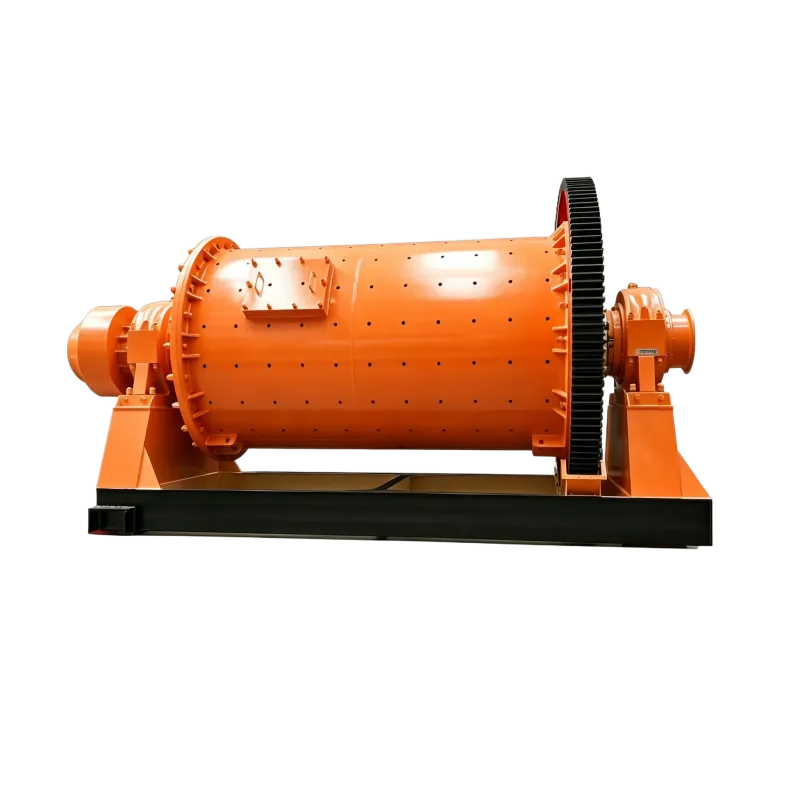
Figure 9‑12 Wet grate discharge ball mill
1 – end cover; 2 – grid plate; 3 – dipper plate (hopper liner); 4 – discharge opening; 5 – center liner; 6 – wedge

Figure 9‑13 Arrangement patterns of grid plate holes
a – concentric arrangement; b – inclined arrangement; c – radial arrangement
From the motion process of the grinding media and material inside the mill, it is known that when the slurry (or fine powder) contacts the grid plate, it moves perpendicularly relative to the radially arranged holes (Figure 9‑13c). The slurry that passes through the holes is not prone to returning to the shell, so clogging often occurs.
For concentrically arranged holes (Figure 9‑13a), the slurry moves along the holes. The holes wear relatively quickly, and the slurry that has passed through the holes may return to the shell, affecting the discharge capacity. However, this arrangement has the advantage of flushing back coarse particles from the holes.
For inclined holes (Figure 9‑13b), the advantages of the previous two arrangements are combined while their disadvantages are mitigated. Therefore, the inclined arrangement is generally preferred. The cross‑section of the grid plate is made trapezoidal. The large end of the trapezoid should face the discharge end cover, which prevents clogging.
The function of the discharge pipe of a grate discharge ball mill is to discharge material and protect the hollow trunnion. For wet grinding, the discharge pipe can be made with a bell‑mouth shape at the outer end to meet the discharge requirements. For dry grinding, a spiral conveying thread is cast (or welded) inside the discharge pipe. The spiral direction should be the same as the mill rotation direction to ensure that the fine powder is discharged from the mill in a timely manner. At present, there are many models and specifications of ball mills manufactured in China. The technical performance of the commonly used wet grate discharge ball mills is listed in Table 9‑4. The meaning of the model and specifications is the same as that for overflow ball mills.
Table 9‑4 Technical performance of wet grate discharge ball mills
| Model | Shell size (D×L) / mm×mm | Effective shell volume / m³ | Ball charge / t | Shell speed / r·min⁻¹ | Power / kW | Discharge particle size / mm | Throughput / t·h⁻¹ | Weight / t | Remarks |
|---|---|---|---|---|---|---|---|---|---|
| MQG1530 | 1500×3000 | 4.0 | 8 | 27.6 | 75 | 0.8~0.074 | 12~2.8 | 15.5 | 380V |
| MQG1535 | 1500×3500 | 4.6 | 11 | 27.6 | 75~90 | 0.8~0.074 | 14~3.4 | 16.3 | 380V |
| MQG1830 | 1800×3000 | 6.5 | 13 | 25.3 | 132 | 0.8~0.074 | 21~4.8 | 28.2 | 380V |
| MQG1835 | 1800×3500 | 7.58 | 16 | 25.3 | 160 | 0.8~0.074 | 25~5.8 | 30.8 | 380V |
| MQG1840 | 1800×4000 | 8.65 | 17.3 | 25.3 | 185 | 0.3~0.074 | 28~6.6 | 33.4 | 6~10kV |
| MQG1845 | 1800×4500 | 9.75 | 19.5 | 25.3 | 210 | 0.3~0.074 | 31~7.2 | 36.2 | 6~10kV |
| MQG2122 | 2100×2200 | 6.7 | 14.7 | 23.8 | 160 | 0.3~0.074 | 24~5.3 | 43.2 | 6~10kV |
| MQG2130 | 2100×3000 | 9.2 | 17 | 23.8 | 185 | 0.3~0.074 | 26~6.0 | 46.8 | 6~10kV |
| MQG2136 | 2100×3600 | 11.0 | 19 | 23.8 | 210 | 0.3~0.074 | 29~6.5 | 49.1 | 6~10kV |
| MQG2140 | 2100×4000 | 12.2 | 20.5 | 23.8 | 220 | 0.3~0.074 | 32~7.2 | 50.2 | 6~10kV |
| MQG2145 | 2100×4500 | 13.8 | 22 | 23.8 | 250 | 0.3~0.074 | 36~8.1 | 51.8 | 6~10kV |
| MQG2424 | 2400×2400 | 9.8 | 20 | 22.8 | 220 | 0.3~0.074 | 32~6.6 | 54.8 | 6~10kV |
| MQG2430 | 2400×3000 | 12.2 | 25 | 22.8 | 250 | 0.3~0.074 | 38~7.5 | 57.8 | 6~10kV |
| MQG2436 | 2400×3600 | 14.6 | 30 | 22.8 | 280 | 0.3~0.074 | 42~8.5 | 60.8 | 6~10kV |
| MQG2440 | 2400×4000 | 16.2 | 33 | 22.8 | 355 | 0.3~0.074 | 47~9.5 | 63.8 | 6~10kV |
| MQG2445 | 2400×4500 | 18.2 | 37 | 22.8 | 400 | 0.3~0.074 | 55~10.5 | 66.3 | 6~10kV |
| MQG2721 | 2700×2100 | 10.7 | 24 | 21.7 | 280 | 0.3~0.074 | 84~8.5 | 66.4 | 6~10kV |
| MQG2727 | 2700×2700 | 13.8 | 29 | 21.7 | 315 | 0.3~0.074 | 105~9.0 | 71.7 | 6~10kV |
| MQG2730 | 2700×3000 | 15.3 | 32.5 | 21.7 | 355 | 0.3~0.074 | 120~10 | 77.3 | 6~10kV |
| MQG2736 | 2700×3600 | 18.4 | 39 | 21.7 | 400 | 0.3~0.074 | 145~12 | 82.4 | 6~10kV |
| MQG2740 | 2700×4000 | 20.5 | 43 | 21.7 | 450 | 0.3~0.074 | 159~13 | 84.73 | 6~10kV |
| MQG2745 | 2700×4500 | 23.0 | 50 | 21.7 | 500 | 0.3~0.074 | 180~15 | 89.1 | 6~10kV |
| MQG3231 | 3200×3100 | 22.65 | 46.9 | 18.6 | 500 | 0.3~0.074 | 182~16 | 139 | 6~10kV |
| MQG3236 | 3200×3600 | 26.20 | 52 | 18.6 | 560 | 0.3~0.074 | 190~19 | 143 | 6~10kV |
| MQG3240 | 3200×4000 | 29.2 | 57 | 18.6 | 630 | 0.3~0.074 | 210~22 | 147 | 6~10kV |
| MQG3245 | 3200×4500 | 32.8 | 65 | 18.6 | 710~800 | 0.3~0.074 | 235~29 | 151 | 6~10kV |
| MQG3254 | 3200×5400 | 39.2 | 81.6 | 18.6 | 800~1000 | 0.3~0.074 | 280~35 | 161 | 6~10kV |
| MQG3640 | 3600×4000 | 35.6 | 75 | 17.3 | 800 | 0.3~0.074 | 230~25 | 185 | 6~10kV |
| MQG3645 | 3600×4500 | 40.8 | 88 | 17.3 | 1000 | 0.3~0.074 | 259~29 | 190 | 6~10kV |
| MQG3650 | 3600×5000 | 45.3 | 96 | 17.3 | 1120 | 0.3~0.074 | 288~35 | 200 | 6~10kV |
| MQG3660 | 3600×6000 | 54.4 | 117 | 17.3 | 1250~1500 | 0.3~0.074 | 310~38 | 220 | 6~10kV |
| MQG3685 | 3600×8500 | 79.0 | 144 | 17.3 | 1800 | 0.3~0.074 | 450~50 | 260 | 6~10kV |
| MQG4040 | 4000×4000 | 45.0 | 82 | 16.4 | 1000 | 230 | 220 | ||
| MQG4050 | 4000×5000 | 57.0 | 161 | 16.4 | 1250 | 270 | 260 | ||
| MQG4560 | 4500×6000 | 85.0 | 162 | 15.42 | 2000 | 285 | 285 | ||
| MQG5264 | 5200×6400 | 123.0 | 229 | 14.3 | 2×1600 | 320 | 350 |


