
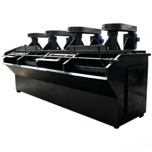
This machine was introduced from the Soviet Union in the 1950s. It is an older design, and although it has undergone some improvements, its basic structure has remained unchanged and has long been standardized into a series. Due to historical reasons, this flotation machine has been the most widely used in China. Although it has been replaced by some newer types of flotation machines in recent years, it is still extensively applied.
This machine was introduced from the Soviet Union in the 1950s. It is an older design, and although it has undergone some improvements, its basic structure has remained unchanged and has long been standardized into a series. Due to historical reasons, this flotation machine has been the most widely used in China. Although it has been replaced by some newer types of flotation machines in recent years, it is still extensively applied.
(1) Structure and Working Principle
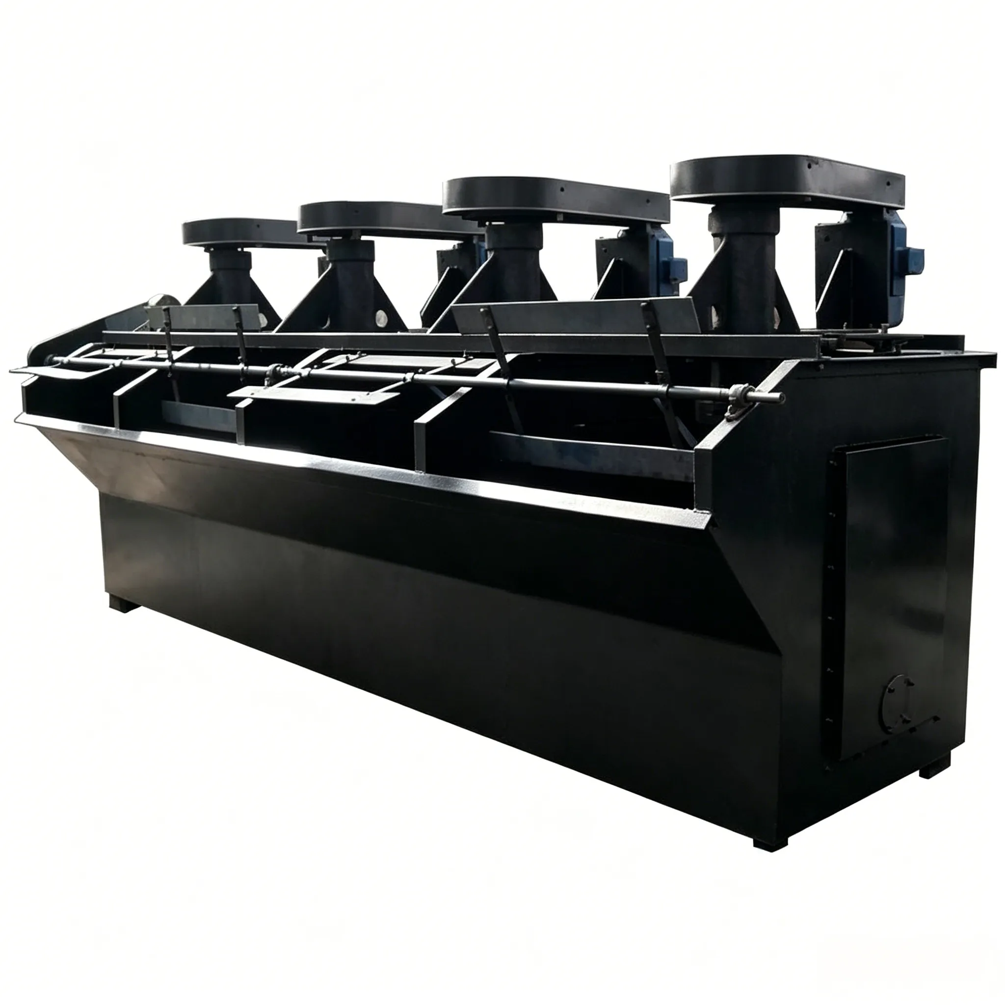
The basic structure of the XJ flotation machine is shown in Figure 12-1. It consists of two flotation cells forming one unit. The first cell (equipped with the feed pipe) is the suction cell, and the second cell is the direct-flow cell. Between these two cells is an intermediate chamber. The impeller is mounted at the lower end of the main shaft, and a belt pulley is installed at the upper end of the main shaft, which is driven by an electric motor. Air is drawn in through the air intake pipe. The pulp level in each group of flotation cells is adjusted by a gate. Above the impeller are a stator (cover plate) and an air standpipe (also known as the vertical pipe). The air standpipe has openings for installing the feed pipe, the middlings return pipe, or for pulp circulation. The size of the openings can be adjusted by a tie rod (pull rod).

Figure 12-1 Structure of the XJ flotation machine
1—Main shaft; 2—Impeller; 3—Cover plate (stator); 4—Connecting pipe; 5—Sand hole gate screw rod; 6—Air intake pipe; 7—Air standpipe; 8—Base plate; 9—Bearing; 10—Belt pulley;
11—Overflow gate handwheel and screw rod; 12—Scraper; 13—Froth overflow lip; 14—Cell tank; 15—Sand discharge gate; 16—Feed pipe (suction pipe);
17—Overflow weir; 18—Overflow gate; 19—Gate housing (outer wall of intermediate chamber); 20—Sand hole; 21—Sand hole gate; 22—Middlings return opening;
23—Front overflow weir of the direct-flow cell; 24—Electric motor and belt pulley; 25—Circulation hole adjusting rod.
The impeller is generally a cast iron disc with six radial blades. A cover plate (stator) is installed 5–6 mm above the impeller, as shown in Figure 12-2.
Functions of the impeller cover plate (stator):

Figure 12-2 XJ flotation machine
(a) Impeller; (b) Cover plate (stator)
1—Impeller conical base; 2—Impeller shell (hub); 3—Radial blades; 4—Cover plate (stator); 5—Guide vanes (stator blades); 6—Circulation holes;
r₁ — Pulp inlet radius; r₂ — Pulp outlet radius; h — Height at the outer end of the blade.
Working principle:
During operation of the flotation machine, the feed pipe delivers the pulp to the center of the cover plate. The centrifugal force generated by the rotating impeller throws the pulp outward, while at the same time creating a negative pressure between the impeller and the cover plate. This negative pressure automatically draws in external air through the air intake pipe. The vigorous agitation of the impeller thoroughly mixes the pulp with the air and breaks the airflow into many fine bubbles. In addition, some bubbles also precipitate from the pulp behind the impeller blades.

Figure 12-3 Overall assembled aerator
(2) Main Features
The main structural and operational features of this flotation machine are as follows:
Because the XJ flotation machine is an older design, it has the following disadvantages:
The XJ mechanical agitation flotation machine can be widely used for roughing, cleaning, scavenging, and reverse flotation of ferrous metal ores (e.g., iron), non‑ferrous metal ores (e.g., copper, lead, zinc, nickel, molybdenum, gold), and non‑metallic minerals. However, it is not suitable for roughing and scavenging operations in large‑scale flotation plants.
Because this flotation machine has been standardized into a series since the 1950s and has been widely used ever since, there are many manufacturers. Its technical specifications are shown in Table 12‑2.
Table 12‑2 Technical specifications of XJ and XJK flotation machines
| Model | XJK‑0.13 | XJK‑0.35 | XJK‑0.62 | XJK‑1.1 | XJK‑2.8 | XJK‑5.8 |
|---|---|---|---|---|---|---|
| Effective volume per cell / m³ | 0.13 | 0.35 | 0.62 | 1.1 | 2.8 | 5.8 |
| Cell length / mm | 500 | 700 | 900 | 1100 | 1750 | 2200 |
| Cell width / mm | 500 | 700 | 900 | 1100 | 1600 | 2200 |
| Cell height / mm | 550 | 700 | 850 | 1000 | 1100 | 1200 |
| Capacity (based on pulp) / m³·min⁻¹ | 0.05–0.16 | 0.18–0.40 | 0.3–0.9 | 0.6–1.6 | 1.5–3.5 | 3.0–7.0 |
| Impeller diameter / mm | 200 | 300 | 350 | 500 | 600 | 750 |
| Impeller speed / r·min⁻¹ | 593 | 483 | 400 | 330 | 280 | 240 |
| Impeller main shaft motor power / kW | 1.5 (per two cells) | 1.5 | 3.0 | 5.5 | 10 | 22 |
| Scraper drive motor power / kW | 0.6 | 0.6 | 1.1 | 1.1 | 1.1 | 1.5 |
| Scraper speed / r·min⁻¹ | 17.5 | 20 | 16 | 26 | 16 | 17 |
Example of model designation meaning:
XJ‑11
X – Flotation machine (Xuan – selection)
J – Mechanical agitation, impeller type
11 – Effective cell volume 1.1 m³


