

Currently, the center-drive thickeners produced in China are relatively small in size, generally with a diameter of less than 20 m. For diameters greater than 20 m, only the φ45 m model is available. For thickeners with a diameter below 12 m, a manual rake lifting mechanism is generally used
Currently, the center-drive thickeners produced in China are relatively small in size, generally with a diameter of less than 20 m. For diameters greater than 20 m, only the φ45 m model is available. For thickeners with a diameter below 12 m, a manual rake lifting mechanism is generally used, while those with a diameter above 12 m are typically equipped with an automatic rake lifting mechanism. To handle corrosive slurries, corrosion-resistant thickeners are also available. To increase processing capacity, thickeners fitted with inclined plates are also produced.
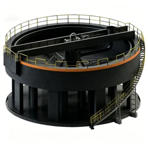
Taking the NZ-20Q center-drive thickener as an example, the general structure of this type of thickener is shown in Figure 14-2. The center-drive thickener mainly consists of a thickening tank, rake mechanism, drive unit, rake lifting device, feed device, discharge device, and safety signaling device.

Figure 14-2 Structure of the NZ-20Q Center-Drive Thickener
1—Truss; 2—Drive unit; 3—Rake lifting device; 4—Feed well; 5—Rake mechanism; 6—Inclined plates; 7—Thickening tank; 8—Annular overflow launder; 9—Vertical shaft; 10—Discharge hopper
The cylindrical thickening tank (7) is made of concrete or steel plate (for smaller units), with the bottom slightly conical or flat. At the center of the tank bottom is a discharge hopper (10) for discharging the thickened product. An annular overflow launder (8) is arranged around the upper periphery of the tank. A vertical shaft (9) is installed at the center of the thickening tank, and a cross‑shaped rake mechanism (5) is fixed at the lower end of the shaft, with scraper blades mounted underneath. The rake mechanism is inclined at an angle of 8° to 15° relative to the horizontal plane. The vertical shaft is rotated by an electric motor mounted on the truss (1) via a cylindrical gear reducer, an intermediate gear, and a worm gear reducer. When the vertical shaft rotates, the slurry flows along the feed chute on the truss into the feed well (4) at the center of the tank and then spreads toward the periphery. The solid particles in the slurry gradually settle to the bottom of the tank and are scraped by the blades under the rake mechanism into the discharge hopper at the center, from which they are discharged by a sand pump. The clarified water overflows from the annular overflow launder (8) at the top of the tank.
To improve thickening efficiency, inclined plates (6) are installed around the periphery of the tank in the lower part of the clarification zone. With the inclined plates, the slurry flow moves diagonally upward through the space between the plates. Solid particles settle vertically between two adjacent plates, shortening the settling distance and reducing settling time. Fine particles that settle onto the inclined plates aggregate together and slide downward along the plates, increasing the settling velocity. The installation of inclined plates also increases the natural settling area of the thickener.
During operation, attention should be paid to the discharge density. Overloading or over‑thickening of the material can cause clogging of the discharge hopper and twisting of the rake mechanism. To prevent such situations, a safety signaling device and a rake lifting device are provided.
Currently, center‑drive thickeners produced in China are available in a variety of types and sizes, including manual‑lift and automatic‑lift rakes, corrosion‑resistant models, and those equipped with inclined plates. Their technical specifications are listed in Table 14‑1. An example of the model and size designation is as follows:

Table 14-1 Technical Performance of NZ Type Central Drive Thickener
| model | Concentration tank/m | Precipitation area ①/m² | “Rack rotation speed per minute” | Rake lifting height/m | production capacity1 ·d-¹ | Motor power (in kW) | Mass/t | remark | |||
| diameter | depth | A | B | transmission | enhance | ||||||
| NZS-1 | 1.8 | 1.8 | 2.54 | one | 2 | 0.16 | 5.6 | 1.1 | one | 1.235 | two |
| NZS-3 | 3.6 | 1.8 | 10.2 | 2.5 | 0.35 | 22.4 | 1.1 | 3.194 | |||
| NZS-6 | 6 | 3 | 28.3 | 3.7 | 0.2 | 62 | 1.1 | 8.751 | |||
| NZSF-6 | 6 | 3 | 28.3 | 3.7 | 0.2 | 62 | 1.1 | 3.646 | |||
| NZS-9 | 9 | 3 | 63.6 | 4.34 | 0.35 | 140 | 3 | 5.1 | |||
| NZ-9 | 9 | 3 | 63.6 | 4.34 | 0.25 | 140 | 3 | 0.8 | 5.134 | ||
| 9 | 4.15 | 63.6 | 4.37 | 0.25 | 160 | 3 | 0.8 | 7.903 | F171 | ||
| NZF-9 | 9 | 3 | 63.6 | 4.34 | 0.25 | 140 | 3 | 0.8 | 5.36 | one | |
| NZS-12 | 12 | 3.5 | 113 | 5.28 | 0.25 | 250 | 3 | one | 8.51 | ||
| 12 | 3.5 | 113 | 5.28 | 0.25 | 250 | 3 | 34.671 | 426B | |||
| 12 | 4 | 113 | 5.28 | 0.25 | 250 | 3 | 9.818 | F172 | |||
| NZF-12Q | 12 | 3.5 | 113 | 244 | 5.26 | 0.25 | 180 | 3 | 12.75 | one | |
| 12 | 3.5 | 113 | 244 | 21 | 0.25 | 180 | 1.1 | 13.18 | F60B | ||
| NZ-15 | 15 | 4.4 | 176 | one | 10.4 | 0.4 | 350 | 5.2 | 2.2 | 21.757 | |
| NZF-15Q | 15 | 4.4 | 176 | 800 | 10.4 | 0.2 | 800 | 5.2 | 2.2 | 32.4 | |
| NZ-20 | 20 | 4.4 | 314 | : | 10.4 | 0.4 | 960 | 5.2 | 2.2 | 24.504 | |
| 20 | 4.4 | 314 | 1400 | 14.7 | 0.4 | 1440 | 5.2 | 2.2 | 104.087 | F61 | |
| NZ-20Q | 20 | 4.4 | 314 | 1400 | 10.4 | 0.4 | 1440 | 5.2 | 2.2 | 43.218 | |
| 20 | 4.4 | 314 | 1400 | 61.97 | 0.4 | 1440 | 5.2 | 2.2 | 45.161 | F30K | |
| 20 | 4.2 | 314 | 1400 | 10.4 | 0.4 | 1440 | 5.2 | 2.2 | 48.988 | F30B | |
| NZF-20 | 20 | 4.4 | 314 | 10.4 | 0.2 | 500 | 5.2 | 2.2 | 25.287 | ||
| NZ-45 | 45 | 4.64 | 1590 | one | 20 | one | 515 | 5.2 | two | 47.81 | |
① A represents the bottom area of the pool; B represents the horizontal projection of the inclined plate.


