
The grinding process of an autogenous mill is illustrated in Figure 10‑1a (taking a dry autogenous mill as an example): After the ore is fed from the feed end, the small particles uniformly fall onto the center of the mill shell bottom along the wave‑shaped liners on surface A and spread to both sides. The large pieces in the feed have greater kinetic energy and tend to reach the farther side; however
The grinding process of an autogenous mill is illustrated in Figure 10‑1a (taking a dry autogenous mill as an example):
After the ore is fed from the feed end, the small particles uniformly fall onto the center of the mill shell bottom along the wave‑shaped liners on surface A and spread to both sides. The large pieces in the feed have greater kinetic energy and tend to reach the farther side; however, some of them strike the liners at A and B and return to the opposite side, thereby also achieving a uniform distribution of the large pieces. The role of the crest liners on surfaces A‑A and B‑B is to prevent segregation of the feed. The medium‑sized particles that return from the discharge end along the lower part of the mill wall also fall uniformly onto the center of the shell bottom and then spread towards the liners on both sides. Both large pieces and fine particles move axially along the bottom of the shell, but in opposite directions, resulting in a crushing action.

Figure 10‑1 Grinding process and material movement in an autogenous mill
a – grinding process of an autogenous mill; b – material movement condition
The lifting bars C‑C and wave liners B‑B have a wedging effect on the ore. The ore is first wedged at C‑C, forming an “arch” along the axial direction, which gradually expands upward. An “arch” also forms between B‑B. Thus, all ore within the arched zone is in a compressed state.
As the ore rotates with the shell, its position rises rapidly, and it quickly changes from a compressed state to a tension state. When the gravity of the ore overcomes the centrifugal force, the ore detaches from the shell and falls. However, the falling paths of different particle sizes are different (Figure 10‑1b). Because large lumps have greater weight, they begin to slide off at a lower height when rising, simultaneously abrading and grinding the small particles, and then move to the inner layer at the center of the shell. Medium‑sized ore rises with the shell to a higher position and then rolls down in a cascading manner, with the ore pieces abrading each other, forming a cascading zone. Small ore pieces rise with the shell to an even higher position and then fall along a parabolic trajectory, forming a cataracting zone, where the impact force crushes the ore into fine particles. Even smaller particles float on the surface layer. In summary, as the shell rotates, during the continuous circulation, the ore is crushed under repeated actions of impact, abrasion, and compression. Particles that meet the product size requirement are carried out by the circulating air stream passing through the autogenous mill (in dry grinding) or discharged with water (in wet grinding).
Construction of a Wet Autogenous Mill
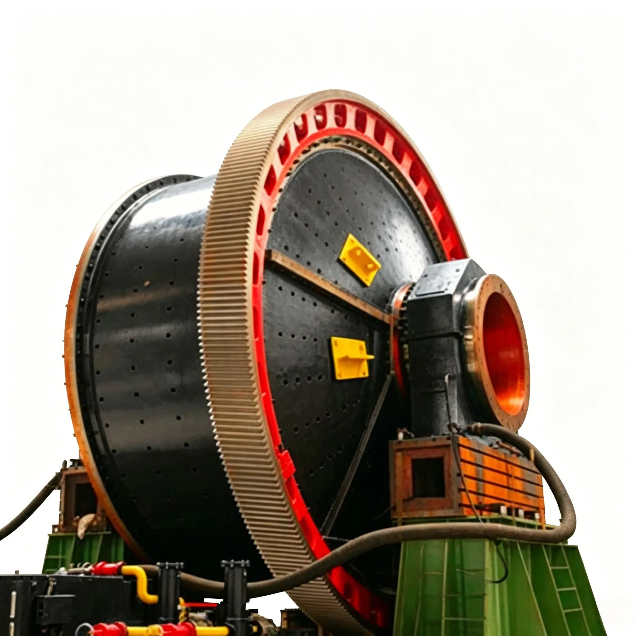
The construction of a wet autogenous mill is generally similar to that of a ball mill, comprising a shell, end covers, liners, discharge section, feed section, bearings, drive unit, lubrication system, etc. Taking the φ5.5 mm × 1.8 mm wet autogenous mill (which has been successfully applied at the concentrator of Luzhong Mining and Metallurgy Group Company since 1985) as an example, its structure is shown in Figure 10‑2.
The feed trolley (1) is a feeding device that receives ore from the conveyor and turns it into the mill. Its upper part is a welded steel plate hopper, and the lower part is supported on a four‑wheel trolley. The shape of the hopper must be able to withstand the impact of large ore blocks while allowing ore to flow smoothly into the mill. The bottom of the hopper, which directly receives the ore impact, is made flat. After ore is fed in, it builds up a natural ore cushion on the flat bottom, completely avoiding direct impact on the hopper. Therefore, no hard wear‑resistant liner or reinforced hopper bottom is required at this location. The lower section of the flat bottom is formed into a chute inclined at about 40° to ensure smooth feeding of ore into the mill.
The shell (4) is assembled with the feed end cover (2) and discharge end cover (8) to form the grinding space. Inside, liners such as the feed end liner (3), shell liner (5), grid plate (6), and dipper plate (7) are fitted. The liners are in direct contact with the ore, so they must be both wear‑resistant and conducive to high grinding efficiency. Therefore, the quality of the liner material and the rationality of its geometry are very important.

Figure 10‑2 Structure of a φ5500 mm×1800 mm wet autogenous mill
1 – feed trolley; 2 – feed end cover; 3 – feed end liner; 4 – shell; 5 – shell liner; 6 – grid plate; 7 – dipper plate; 8 – discharge end cover; 9 – self‑returning device
The feed end liner (Figure 10‑3) is directly subjected to the impact of large ore blocks just entering the mill, as well as to abrasion from the returning moving ore. Therefore, its wear is rapid. To prevent ore from impacting the liner surface, a wave crest 250 mm high is provided at the end of the liner near the center. To prevent wear from the circular movement of the ore, guard ribs with an 80 mm × 80 mm cross‑section are provided on the outer ring liner. Practice has shown that increasing the wave crest height to 330 mm and adding guard ribs on the inner ring as well can extend the liner life by 2 to 2.5 times.

Figure 10‑3 Feed end liner
a – liner with half‑length guard ribs and low wave crest; b – liner with full guard ribs and high wave crest
Grid plate (Figure 10‑4) in an autogenous mill not only serves to discharge material but also performs a screening function. Therefore, both the position of the grid holes and the hole size must be selected appropriately. Depending on the overflow level at which the slurry can be discharged through the grid holes, they can be classified into high‑level discharge (uncommon), medium‑level discharge (Figure 10‑4, No. 1), and low‑level discharge (Figure 10‑4, No. 3). Under normal material filling ratios of about 45 %, the medium‑level discharge position generally meets discharge requirements. However, autogenous mills often experience low filling ratios (below 20 %), which may result in failure to discharge. Therefore, both medium‑level and low‑level discharge are currently used.
Guard ribs and wave crest plates play the same role on grid plates as on other liners. Practice has shown that a grid plate with guard ribs of 80 mm × 80 mm cross‑section has a service life twice as long as a flat plate without guard ribs. Increasing the wave crest height from 250 mm to 350 mm doubles the service life.
The shell is lined with ordinary flat liners and T‑shaped liners (see Figure 10‑5). T‑shaped liners primarily lift the material and are therefore also called lifting bars. The height and spacing of the lifting bars have a significant effect on the material trajectory. When the lifting bar height is increased from 80 mm to 100 mm, the service life is extended by half, throughput is significantly increased, and the product particle size becomes somewhat coarser. Therefore, both the height of the lifting bars and the ratio of height to spacing must be appropriate to achieve the highest production capacity and the lowest energy consumption.
Figure 10‑4 Grid plate (caption – as inferred from the description; the original does not provide an explicit caption, but you may use:)
Figure 10‑4 Grid plate
(Note: The numbers 1 and 3 mentioned in the text refer to medium‑level and low‑level discharge positions, but are not described in a separate caption.)
Figure 10‑5 T‑shaped liner / lifting bar (caption – as inferred)
Let me know if you need the actual figure captions (e.g., if the original includes specific labels) or any further translation.

Figure 10‑4 Grid plate
1 – medium‑level discharge, low wave crest, grid plate without guard ribs; 2 – blank plate (blind plate); 3 – low‑level discharge, high wave crest, grid plate with guard ribs

Figure 10‑5 Shell liner
1 – lifting bar (lifter); 2 – flat liner
The suitable height is H = 90–110 mm, and the appropriate ratio is L/H = 4–5.
At present, the commonly used liner materials in China are high‑manganese steel and hard steel. Even with the same material and the same manufacturer, different manufacturing processes can result in a service life difference of up to 1.5 times between good‑quality and poor‑quality liners.
The above practice shows that the structural shape and manufacturing quality of liners have a very significant impact on service life. Providing guard ribs of appropriate height on the liner surface is an effective method to reduce relative sliding between the ore and the liner surface, reduce wear, and extend service life. Once the guard ribs (including the lifting bars on the shell) are worn flat, the flat portions will wear away rapidly. Therefore, liners should not be excessively thick. The crest height of wave plates must be appropriate; if the crest is too high, it can be struck by large ore blocks and become loose. The height should be such that the plate surface is not directly impacted by the ore.
Discharge and self‑return device
The product discharged from a wet autogenous mill is slurry, so it is equipped with a grate discharge device – something that dry autogenous mills do not have. Its structure is the same as that of a grate discharge ball mill.
At the discharge end, the autogenous mill has a material self‑return device (Figure 10‑6), which is essentially a classifying device. It consists of a drum screen (1), a sand return pipe (2), and a sand return scoop (3).
After the slurry passes through the grid plate holes, it is fed by the dipper plates behind the grid plate onto the screen of the self‑return device. Coarse material moves on the screen to the sand return scoop at the other end. During the rotary motion of the scoop, the coarse material is fed into the sand return pipe. The spiral vanes inside the sand return pipe push the coarse material back into the mill for regrinding. The undersize material (passing the screen) is discharged through the discharge bushing for further processing.
This classifying device is simple in structure and works well. With a single screen deck, it can separate material below 20–30 mm into a product below 3–5 mm. Installing this device allows the use of larger grid plate openings (or eliminates the need for difficult‑to‑manufacture small holes), increases the flow rate (throughput) of material, and thus improves grinding efficiency. Of course, this closed circuit apparently only operates at the discharge end, without a full‑length grinding process through the entire shell. However, because autogenous mills have a large diameter, short length, and wave crest plates, the material movement in an autogenous mill is not like that in a ball mill – where material moves progressively and orderly from the feed end to the discharge end while being gradually ground down. Instead, materials from both ends cross over or are thrown into the middle of the mill. Therefore, although there is some difference in grinding efficiency between the sand returned from the discharge end and the sand returned from the feed end, the difference is not significant. The extent to which the use of a self‑return screen for size control differs from the use of grid plate openings for size control requires further experimental study.
This closed‑circuit classifying device can also be modified into an open‑circuit classifying device. This is done by changing the discharge direction of the sand return scoop to outward, or by removing the scoop altogether, collecting the screen oversize and sending it directly to secondary grinding or other treatment. The screen undersize can be processed for beneficiation.

Figure 10‑6 Self‑return device
1 – drum screen; 2 – sand return pipe; 3 – sand return scoop
In the transmission (drive) system, earlier models of wet autogenous mills had the large gear mounted on the hollow trunnion at the discharge end. With advances in manufacturing technology, the large gear is now fixed directly onto the shell of the autogenous mill.
In the lubrication system, wet autogenous mills use a central circulating oil lubrication system. Large wet autogenous mills also employ a new technology – spray lubrication.
In recent years, the manufacturing technology for wet autogenous mills in China has developed rapidly. Mills of various types and sizes can now be produced to meet the requirements of different ore types and production scales, and they are also exported abroad. The technical performance of wet autogenous mills currently produced in China is shown in Table 10‑1. An example explaining the meaning of the model and specifications is as follows:

Table 10‑1 Technical performance of autogenous mills
Table 10‑1 Technical performance of autogenous mills
| Model | shell size /mm | feed size/mm | output size/mm | capacity /t ·h⁻ | sheel speed /r ·min⁻¹ | power /kW | weigh/t | |
| diameter | length | |||||||
| MZS2.4×1.0 | 2400 | 1000 | <250 | 3~0.074 | 10~3.5 | 16~22 | 75 | 18.5 |
| MZS2.4×1.2 | 2400 | 1200 | <250 | 3~0.074 | 12-4.0 | 16-22 | 90 | 19.1 |
| MZS3.0×1.0 | 3000 | 1000 | <300 | 3-0.074 | 18~5.0 | 19.5 | 132 | 28.6 |
| Model | shell size/mm | feed size/mm | output size/mm | capacity /t·h⁻ | sheel speed /r ·min⁻¹ | power /kW | weigh/t | |
| diameter | length | |||||||
| MZS3.2×1.2 | 3200 | 1200 | <300 | 3~0.074 | 20~8.0 | 19.0 | 160 | 37.4 |
| MZS4.0×1.4 | 4000 | 1400 | <350 | 3~0.074 | 70~25 | 18.0 | 250 | 66.0 |
| MZS5.5×1.8 | 5500 | 1800 | <400 | 3~0.074 | 130~55 | 15.0 | 800 | 179.0 |
| MZS6.0×3.0 | 6000 | 3000 | <400 | 3-0.074 | 1250 | |||
| MZS6.4×3.3 | 6400 | 3300 | <400 | 3-0.074 | 290-90 | 12.8 | 2000 | 306.0 |
| MZS7.5×2.5 | 7500 | 2500 | <400 | 3-0.074 | 300-100 | 11.4 | 2000 | 455.0 |
| MZS7.5×2.8 | 7500 | 2800 | <400 | 3-0.074 | 380~125 | 11.4 | 2000 | 464.0 |
| MZS8.0×2.8 | 8000 | 2800 | <400 | 3~0.074 | 282 | 12.4 | 3000 | 510.0 |
| MZS8.53×3.96 | 8530 | 3960 | <400 | 4850 | ||||
| MZS8.53×4.27 | 8530 | 4270 | <400 | 5000 | ||||
| MZS8.8×4.8 | 8800 | 4800 | <400 | 6000 | ||||
| MZS9.75×4.27 | 9750 | 4270 | <400 | 4250×2 | ||||
| MZS10.37×5.11 | 10370 | 5110 | <400 | 5600×2 | ||||
| MZS12.2×11 | 12200 | 11000 | <400 | 28000滑环 | ||||


