
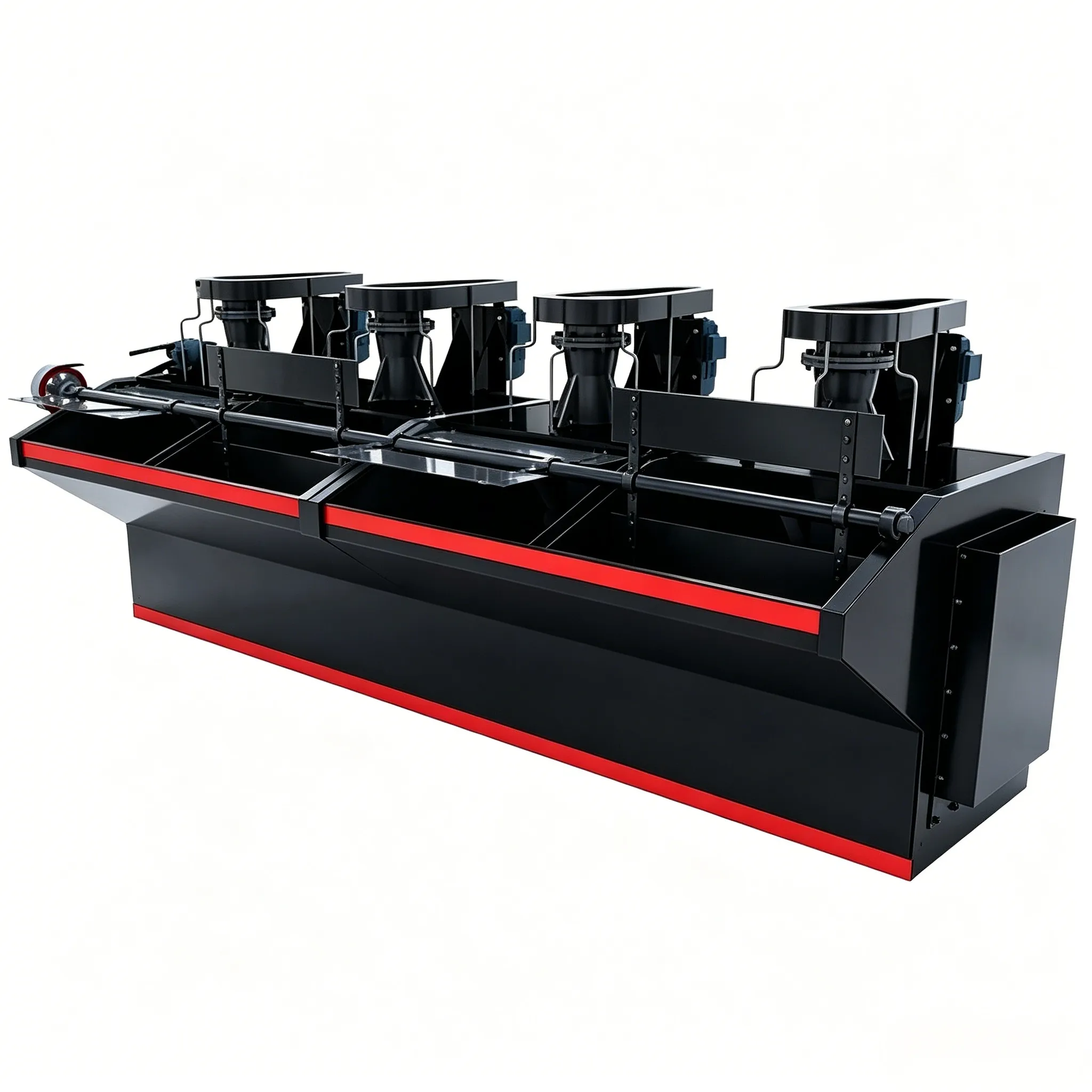

Its agitation and aeration device consists of 12 inclined round rods, hence the name “rod‑type flotation machine”. The structure of this machine is shown in Figure 12‑10.
The rod‑type flotation machine has two types: the direct‑flow cell and the suction cell. The direct‑flow cell is equipped with a hollow shaft (main shaft), a rod‑type rotor, a boss, and an arc‑shaped flow stabiliser. The direct‑flow cell cannot draw pulp from the bottom and serves only for flotation; it is also called a flotation cell.
The XJB rod‑type flotation machine is similar to the Australian Warman type flotation machine.
(1) Structure and working principle of the XJB rod‑type flotation machine
Its agitation and aeration device consists of 12 inclined round rods, hence the name “rod‑type flotation machine”. The structure of this machine is shown in Figure 12‑10.
The rod‑type flotation machine has two types: the direct‑flow cell and the suction cell. The direct‑flow cell is equipped with a hollow shaft (main shaft), a rod‑type rotor, a boss, and an arc‑shaped flow stabiliser. The direct‑flow cell cannot draw pulp from the bottom and serves only for flotation; it is also called a flotation cell. The suction cell is equipped with a pulp‑suction impeller installed below the rod‑type rotor, which can draw pulp from the bottom like a centrifugal pump. A suction cell is installed at the feed point of each operation, such as roughing, cleaning, and scavenging.
When the direct‑flow cell is in operation, the rotation of the inclined rod‑type rotor below the hollow shaft causes the pulp to be strongly ejected toward the bottom and around the cell at a certain cone angle, thereby creating a negative pressure under the inclined rod rotor. External air is then drawn in through the hollow shaft. Under the action of the inclined rod rotor, the pulp and air are thoroughly mixed, while the air stream is cut and dispersed into fine bubbles. The boss acts as a guide, directing the pulp‑air mixture rapidly toward the bottom of the cell. After being stabilised by the arc‑shaped flow stabiliser, the mixture moves toward the periphery of the cell and is uniformly distributed throughout the cell, while the rotating pulp‑air flow is transformed into a nearly radial flow. The stabilised pulp then turns from the bottom and rises slowly toward the liquid surface. Thus, the pulp‑air mixture follows a special “W”‑shaped flow path inside the cell, making the pulp surface relatively stable. The mineralised bubbles rise to the froth zone and are scraped out as froth product.

Figure 12‑10 Structure of the XJB‑10 rod‑type flotation machine
1—Main shaft; 2—Inclined rod rotor; 3—Boss; 4—Flow stabilizer; 5—Pulp guide pipe; 6—Base plate
(2) Main features
The main feature of the rod‑type flotation machine is that the aeration agitator assembly consists of an inclined rod rotor, a boss, and an arc‑shaped flow stabiliser.

Figure 12‑11 Structural features of the rod‑type flotation machine
(a) Inclined rod rotor; (b) Boss and arc‑shaped flow stabiliser
Because this agitator prevents sanding at the cell bottom and has very few dead zones, the cell volume is fully utilised, significantly improving the volumetric efficiency. Since the aerated pulp follows a W‑shaped flow path, the installation depth of the rod rotor in the cell can be reduced. This not only makes it easier to restart after prolonged shutdowns but also helps increase aeration, reduce power consumption, and improve the technical performance of the flotation machine.
In addition, this flotation machine also has the advantages of simple structure, easy operation and maintenance, high bubble dispersion, more frequent pulp‑air contact, uniform mixing, and fast flotation speed.
The XJB rod‑type flotation machine is suitable for small‑ and medium‑sized concentrators processing high‑density, coarse‑grained metal ores. It can be used in various flotation operations and is particularly effective for separating lead, zinc, copper, molybdenum, sulfur, and silica sand. Its technical performance is shown in Table 12‑9.
Example of model designation meaning:
XJB‑10D
X – Flotation machine
J – Mechanical agitation
B – Rod type
10 – Cell volume 1.0 m³
D – Single‑sided froth scraping
(For double‑sided froth scraping, no letter is added after the model.)
Table 12-9 Technical Performance of XJB Rod-type Flotation Machine
| Model | XJB-10(XJB-10D)① | XJB-20(XJB-20D)① | XJB-40(XJB-40D)① | ||||
| Specification / m³ | 1 | 2 | 4 | ||||
| Tank assembly | Flotation cell | Inhalation slot | Flotation cell | “Suction slot” | Flotation cell | Suction slot | |
| Slot inner wall dimensions (length × width × height) / mm × mm × mm | 1300×1300×680 | 1750×1750×700 | 2200×2200×800 | ||||
| Wheel diameter/mm | Flotation wheel | 410 | one | 540 | one | 700 | one |
| Grout suction wheel | one | 400 | one | 450 | one | 510 | |
| Gap /mm | Between the flotation machine and the boss | 25-30 | 20~25 | 35~45 | 30~40 | one | one |
| Between the slurry suction wheel and the chassis | one | 5~10 | one | 8~18 | one | one | |
| speedRed · min⁻¹ | Main shaft | 410 | 440 | 360 | 280 | ||
| Scraper | 17;22 | 12.5(16) | one | ||||
| Processing capacity (slurry flow rate) / m³ ·min- | 1.5~1.7 | 1.5~4 | 2-4 | ||||
| Overall dimensions/mm | long | one | |||||
| wide | 1684 | 2173 | one | ||||
| high | 1906 | 2142 | one | ||||
| For use with the main shaftelectric motor | Model | Y132M₂-6 | Y132S-4 | Y160L-6 | Y180L-6 | two | |
| Power/kW | 4 | 5.5 | 11 | 15 | 18.5 | ||
| Number of units | One unit per slot | One unit per slot | One unit per slot | One unit per slot | one | ||
| For scraperelectric motor | model | Y90S-4 | Y90S-4 | Y90L-6 | one | ||
| Power / kW | 1.1 | 1.1 | 1.1 | one | |||
| Number of units | One unit per column | One unit per column | one | ||||
| General Drawing Number | A199P(A117P) | A106P(A127P) | one | ||||
| Instructions | This equipment is divided into single-sided foam scraping(XJB-10D, A117P) and double-sided bubble scraper (XJB-10, A99P) | This equipment is divided into unilateral bubble scraping(XJB-20D, A127P) and double-sided bubble scraper (XJB-20, AI06P) | one | ||||
The data within ① represents unilateral froth scraping; every two tanks include one flotation tank and one suction tank.


