
The pulp discharged from the grinding mill flows through a launder into the feed inlet located in the middle of the settling zone of the water tank
The pulp discharged from the grinding mill flows through a launder into the feed inlet located in the middle of the settling zone of the water tank. The lower part of the water tank, which is installed at an incline, serves as the pulp classification and settling zone. The spiral rotates at a low speed, stirring the pulp so that light and fine particles remain suspended and rise to the top, then flow over the overflow weir and proceed to the next process step. Coarse and heavy particles settle to the bottom of the tank and are conveyed by the spiral to the discharge port, where they are discharged as returned sand (sands). Typically, the coarse sand is returned to the mill for regrinding, i.e., the spiral classifier and the grinding mill form a closed circuit. The working principle is shown in Figure 11-1.

Figure 11-1 Working principle of the spiral classifier
Types of Spiral Classifier
Spiral classifiers can be divided into single-spiral and double-spiral types according to the number of spiral shafts. According to the height of the overflow weir, they can be divided into three types: high weir, low weir, and submerged. Specifically, when the overflow weir is located above the bearing center of the lower end of the spiral shaft but below the upper edge of the spiral at the overflow end, it is called a high-weir spiral classifier. It has a certain settling zone and is suitable for coarse particle classification, capable of producing an overflow product with a particle size greater than 0.83–0.15 mm. When the overflow weir is below the bearing center of the overflow end, it is called a low-weir spiral classifier. Its settling zone area is small and its overflow capacity is low; it is generally not used for classification but for washing ore sand and desliming. When the entire spiral at the overflow end is submerged below the liquid surface of the settling zone, it is called a submerged spiral classifier. Its settling zone has a relatively large area and depth, making it suitable for fine particle classification, capable of producing an overflow product with a particle size of less than 0.15–0.07 mm.
At present, spiral classifiers in China have developed into a complete product series and are widely used in grinding and classification operations in various mineral processing plants. Their technical parameters are listed in Table 11-1.
Example of spiral classifier model and specification:
2 FG-152 — Double spiral (single spiral is not marked); F — Classifier (a few manufacturers write FL); G (C) — High weir type (submerged type); 15 — Spiral diameter, dm (a few manufacturers write 1500 mm).
Table 11-1 Technical parameters of spiral classifier
| Type | model | spiral diameter/mm | Tank length/mm | spiral speed r·min⁻¹ | capacity/t·h-1 | tank slope/(°) | Spiral weight/t | Power/kW | weigh/kg | ||
| Return sand | Overflow | Drive motor | Hoist motor | ||||||||
| High-weir spiral classifier | FG300 | 300 | 8.3~22 | 30~80 | 10~30 | 14-18 | 1.1 | 668 | |||
| FG500 | 500 | 4500 | 8-12.5 | 135~210 | 32 | 14-18.5 | 0.75 | 1.5 | 1980 | ||
| FG750 | 750 | 5500 | 6.0~10.0 | 340~570 | 65 | 14-18.5 | 1.1 | 3.0 | 3005 | ||
| FG-1000 | 1000 | 6500 | 5.0-8.0 | 675~1080 | 110 | 14-18.5 | 1.9 | 7.5 | 5310 | ||
| FG-1200 | 1200 | 6500 | 5.0~8.0 | 1170-1870 | 155 | 14~18.5 | 3.7 | 7.5 | 0.4 | 8000 | |
| FG-1500 | 1500 | 8300 | 4.0-6.0 | 1830-2740 | 235 | 14-18.5 | 5.1 | 11 | 0.4 | 9800 | |
| FG-2000 | 2000 | 8400 | 3.0~3.5 | 3240-5400 | 400 | 14-18.5 | 7.1 | 11 | 2.8 | 20500 | |
| FG-2400 | 2400 | 9200 | 2.5-4.0 | 4650~7450 | 580 | 14~18.5 | 10.2 | 11~15 | 2.8 | 25700 | |
| 2FG-1200 | 1200 | 6500 | 5.0~8.0 | 2340-3740 | 310 | 14-18.5 | 3.7×2 | 5.5×2 | 0.4×2 | 13300 | |
| 2FG-1500 | 1500 | 8300 | 4.0~6.0 | 3660-5480 | 470 | 14-18.5 | 5.1×2 | 7.5×2 | 0.4×2 | 22100 | |
| 2FG-2000 | 2000 | 8400 | 3.0~5.5 | 6480~10800 | 800 | 14-18.5 | 7.1×2 | 11×2 | 2.8×2 | 36500 | |
| 2FG-2400 | 2400 | 9200 | 2.5~4.0 | 9300~14900 | 1160 | 14-18.5 | 10.2×2 | 15×2 | 2.8×2 | 45800 | |
| 2FG-3000 | 3000 | 12500 | 2.0.~3.2 | 14600~23400 | 1785 | 14~18.5 | 20×2 | 18.5×2 | 4×2 | 73000 | |
| Submerged spiral classifier | FC-1000 | 1000 | 7600 | 5.0~8.0 | 675-1080 | 85 | 14-18.5 | 2.4 | 7.5 | 0.4 | 6000 |
| FC-1200 | 1200 | 8400 | 5.0~8.0 | 1170~1870 | 120 | 14~18.5 | 4.8 | 7.5 | 0.4 | 9280 | |
| FC-1500 | 1500 | 10500 | 4.0~6.0 | 1830-2740 | 185 | 14~18.5 | 6.4 | 11 | 0.8 | 12570 | |
| FC-2000 | 2000 | 12900 | 3.0-3.5 | 3240~5940 | 320 | 14-18.5 | 8.6 | 11~15 | 2.8 | 29100 | |
| FC-2400 | 2400 | 14200 | 2.5-4.0 | 4650~7450 | 455 | 14-18.5 | 12.8 | 11-18.5 | 4.0 | 41000 | |
| 2FC-1200 | 1200 | 8400 | 5.0-8.0 | 2340-3740 | 240 | 14~18.5 | 4.8×2 | 7.5×2 | 0.4×2 | 19600 | |
| 2FC-1500 | 1500 | 10500 | 4.0-6.0 | 3660-5480 | 370 | 14-18.5 | 6.4×2 | 7.5×2 | 0.8×2 | 30700 | |
| 2FC-2000 | 2000 | 12900 | 3.0~5.5 | 6480-11800 | 640 | 14-18.5 | 8.6×2 | 15×2 | 2.8×2 | 50000 | |
| 2FC-2400 | 2400 | 14200 | 2.5-4.0 | 9300~14900 | 910 | 14~18.5 | 12.8×2 | 18.5×2 | 4×2 | 67900 | |
| 2FC-3000 | 3000 | 14300 | 2.0~3.2 | 14600~23400 | 1410 | 14-18.5 | 24.1×2 | 22×2 | 4×2 | 84900 | |
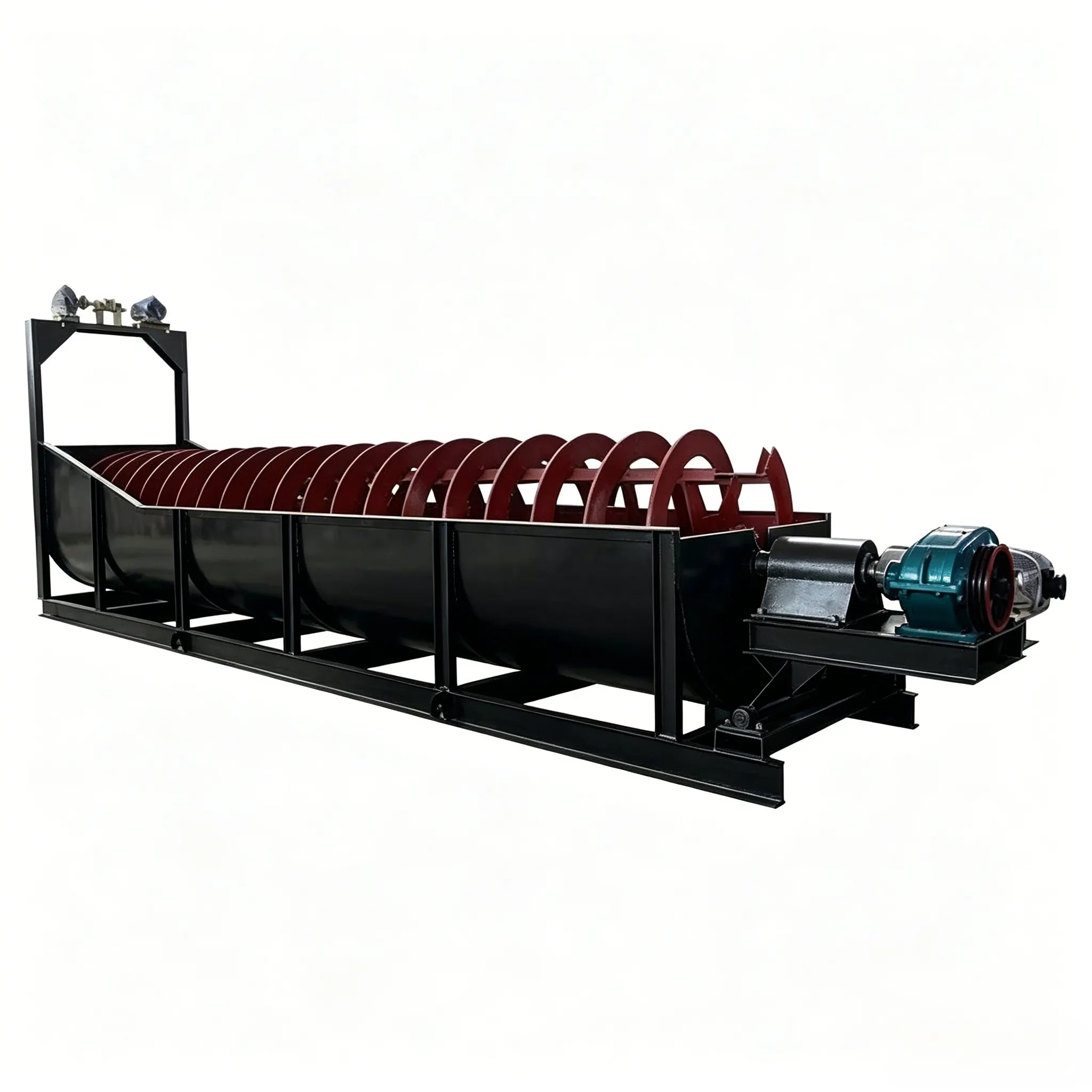
Structure of Spiral Classifier
Taking the high-weir double-spiral classifier as an example, its structure is shown in Figure 11-2. The semi-circular water tank (2) is welded from steel plates and structural steel sections. A feed inlet is provided on the side wall in the middle of the tank, and a sand return opening is located at the lower part of the upper end of the tank. A drain valve is provided at the bottom of the lower end of the tank; this valve is closed during normal operation and opened when the tank needs to be emptied for maintenance. Inside the tank, a longitudinal hollow shaft is installed. On the shaft, left and right brackets corresponding to the spiral lead angle are fixed by means of clamps, and left and right large spiral blades are fixed on these brackets. The spiral mechanism mostly adopts a double-start equal-pitch spiral, and wear-resistant small blades are attached to the edges of the large blades. The hollow shaft is usually made of thick-walled seamless steel pipe; large-diameter hollow shafts are formed by rolling long steel plates into shape and then welding. Both the upper and lower ends of the hollow shaft are welded with journals. The upper end is supported inside a crosshead bushing, and the lower end is supported in a lower bearing support. The crosshead bushing support is shown in Figure 11-3. The journal of the support is supported on the transmission frame, allowing the spiral to be raised or lowered and also supporting the rotation of the spiral shaft.


Figure 11-2 High-weir double-spiral classifier
1—Transmission device; 2—Water tank; 3—Left and right spiral shafts; 4—Feed inlet;
5—Lower support (bottom bearing support);6—Lifting device (raising/lowering mechanism)
The lower bearing support is submerged in the pulp and supports the rotation of the spiral shaft. Its sealing requirements are relatively high. Two sealing devices are commonly used nowadays: a labyrinth packing combined with high-pressure grease lubricated rolling bearing support (Figure 11-4), and a water-sealed rubber bearing support. The rolling bearing support, if properly lubricated and maintained, can have a service life of over one year. The water-sealed rubber bearing support has a lower cost and a service life of about three months.
The spiral shaft is driven by an electric motor, reducer, cylindrical gear and bevel gear pair. The transmission device is mounted at the upper end of the equipment. Since after the equipment is shut down, the settled sand may bury the lower blades and cause difficulty in starting, a spiral shaft lifting mechanism is provided at the tail end. This mechanism uses a motor, reducer, and bevel gear pair to drive a screw rod to raise or lower the shaft.

Figure 11-3 Crosshead bushing support
1—Shaft;2—Support (bracket); 3—Bush (bearing liner);4—Thrust bearing;5—Gland (packing gland);6—End cover

Figure 11-4 Rolling bearing support with combined labyrinth packing and high-pressure grease sealing
1—Labyrinth packing;2—Support base (bearing housing);3—Rolling bearing;4—Shaft


