
These three types of flotation machines are essentially identical and were developed based on the American Wemco flotation machine.
(1) Structure and Working Principle
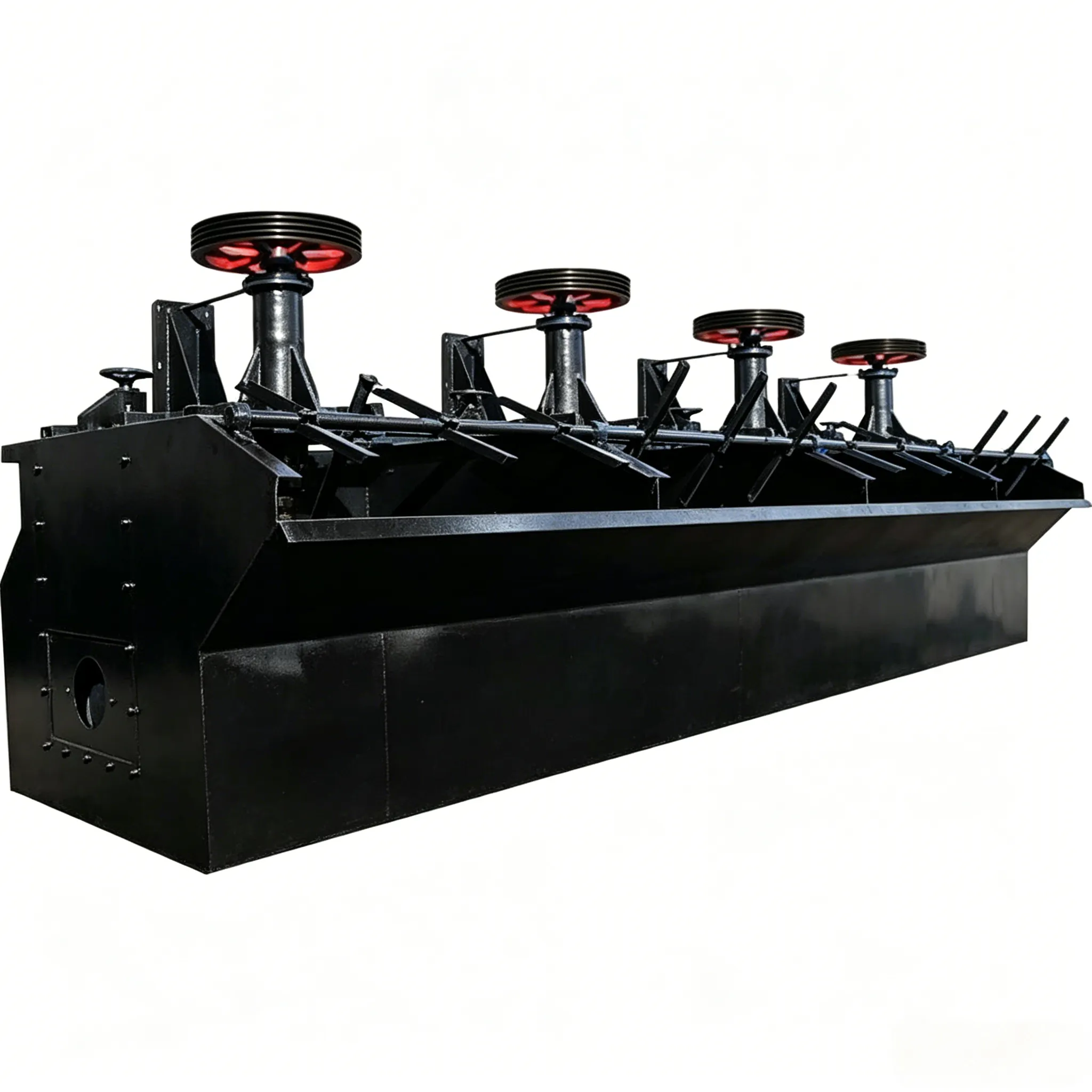
The structures of the XJQ and JJF flotation machines are shown in Figure 12-4. They mainly consist of a cell tank, impeller, stator, dispersion cover, false bottom, draft tube, vertical standpipe, adjusting ring, and other components.
These three types of flotation machines are essentially identical and were developed based on the American Wemco flotation machine.
(1) Structure and Working Principle
The structures of the XJQ and JJF flotation machines are shown in Figure 12-4. They mainly consist of a cell tank, impeller, stator, dispersion cover, false bottom, draft tube, vertical standpipe, adjusting ring, and other components.

Figure 12‑4 Structures of XJQ and JJF flotation machines
(a) XJQ type; (b) JJF type
1—Cell tank; 2—False bottom; 3—Draft tube; 4—Adjusting ring; 5—Impeller; 6—Stator; 7—Dispersion cover; 8—Vertical standpipe; 9—Bearing housing; 10—Electric motor
When the impeller rotates, a vortex is created inside the vertical standpipe and the draft tube. This vortex generates a negative pressure that draws air through the air intake pipe. The air is then mixed with the pulp, which is sucked in through the draft tube, in the impeller and stator zone. The pulp‑air mixture is thrown into tangential motion by the impeller, then converted into radial motion by the stator and evenly distributed throughout the flotation cell. Mineralized bubbles rise to the froth layer and are scraped out from one side or both sides as the froth product.
(2) Main features
The structural and operational features of these two flotation machines are as follows:

Figure 12-5 Pulp flow pattern and aeration-agitation tank of XJQ and JJF flotation machines
(a) Pulp flow pattern; (b) Aeration agitator
1—Stator; 2—Impeller
Other advantages of this flotation machine include high mineral recovery, large processing capacity, wide particle size range, low reagent consumption, low maintenance cost, and reliable performance. Its disadvantage is that it cannot self-absorb pulp; therefore, a froth pump is required for returning the middlings.
The XJQ and JJF flotation machines are currently advanced, new-type flotation equipment in China. They can be widely used for separating non-ferrous metals, ferrous metals, and non-metallic minerals, and are suitable for roughing and scavenging operations in large and medium-sized flotation plants. Their technical performance parameters are shown in Table 12-3.
Example of model designation meaning:
XJQ‑80
X – Flotation machine (Xuan)
J – Mechanical agitation
Q – Shallow cell (Qian cao)
80 – Cell volume 8 m³
Table 12‑3 Technical performance parameters of XJQ flotation machine
(Table content not provided in the original text)
| Model | XJQ-40 | XJQ-80 | XJQ-160 | XJQ-280 |
| Specification/m³ | 4 | 8 | 16 | 28 |
| Inner wall dimensions of the cell/mm×mm×mm | 1600×2100×1350 | 2200×3000×1400 | 2800×3800×1700 | 3000×4150×2400 |
| Effective volume per cell/m³ | 4 | 8 | 16 | 28 |
| Model | XJQ-40 | XJQ-80 | XJQ-160 | XJQ-280 | ||||
| Impeller | diameter/mm | 400 | 560 | 700 | 760 | |||
| rotation/r · min⁻ | 290;315 | 205;225 | 170;180 | 166;185 | ||||
| Peripheral speed/m · s- ¹ | 6.1;6.6 | 6;6.6 | 6.2;6.6 | 一 | ||||
| Radial clearance between impeller and stator/mm | 110 | 160 | 185 | 二 | ||||
| Scraper speed/r · min⁻¹ | 16 | 20 | 16 | 一 | ||||
| Air suction volume/m³ ·min⁻¹ | 0.1-1 | 0.1~1 | ||||||
| capacity/m³ · min⁻¹ | 2~5 | 4.2-10 | 8~20 | 14~35 | ||||
| dimension/mm | width | 2640 | 3180 | 4040 | 一 | |||
| high | 2803 | 3090 | 3528 | 一 | ||||
| weigh,length | figure 12-4 | |||||||
| Reducer model | HWT-100 | HWT-100 | ||||||
| Motor | Main drive | Model | Y160L-6 | Y200L₂-6 | Y250M-8,Y2805-8 | |||
| Power/kW | 11 | 22 | One unit per cell, 30 or 37 | 55 | ||||
| Scraper | Model | Y90L-6 | BWD1.1-2-71 | Y100L-6 | ||||
| Power/kW | L.1 | 1.1 | One unit per cell, 1.5 (kW) | |||||
| Electric gate | Model | Y801-4 | Y801-4 | Y801-4 | ||||
| Power/kW | 0.55 | 0.55 | 0.55 | |||||
| General assembly drawing number | B24AP | B23P | B24P | |||||
JJF‑II flotation machine – Initially, there were four models: JJF‑1, JJF‑2Ⅱ, JJF‑3Ⅱ, and JJF‑4Ⅱ. In recent years, the number of models has been continuously increased, and now there are 14 models with volumes ranging from 42 m³ to 160 m³. They can form combined units with JJF flotation machines of the same specification, enabling horizontal layout between operations without the need for froth pumps, and offering easier operation and maintenance. The JJF‑II flotation machine can also be used alone with very good results.
The characteristics of the JJF‑II flotation machine are as follows:
Its technical parameters are listed in Table 12‑4.
Table 12‑4 Technical parameters of the JJF‑II flotation machine
| Model | volume/m³ | Cell dimensions (length × width × height)/m×m×m | Installed power kW | Air suction volume /m³·m-²·min-¹ | Scraper motor speed /r·min-¹ | capacity/m³ ·min-¹ | cell weigh/kg |
| Suction cell-1 | 1 | 1.10×1.10×1.00 | 5.5 | 1.0 | 18 | 0.3~1 | 1270 |
| Direct-flow cell-1 | 5.5 | 1480 | |||||
| Suction cell-2 | 3 | 1.40×1.40×1.15 | 7.5 | 1.0 | 18 | 0.5~2 | 1750 |
| Direct-flow cell-2 | 7.5 | 1960 | |||||
| Suction cell-3 | 3 | 1.50×1.85×1.20 | 11 | 1.0 | 18 | 1~3 | 2150 |
| Direct-flow cell-3 | 11 | 2430 |
| Model | Volume/m³ | Cell dimensions (length × width × height)/m×m×m | Installed power kW | Air suction volume/ m³·m²·min⁻¹ | Scraper motor speed/s ·min⁻¹ | capacity/ m³·min⁻¹ | cell weigh/kg |
| Suction cell-4 | 4 | 1.60×2.15×1.25 | 15 | 1.0 | 16 | 2~4 | 2585 |
| Direct-flow cell-4 | 11 | 2790 | |||||
| Suction cell-8 | 8 | 2.20×2.90×1.40 | 30 | 1.0 | 16 | 4~8 | 4130 |
| Direct-flow cell-8 | 22 | 4420 | |||||
| Suction cell-10 | 10 | 2.20×2.90×1.70 | 30 | 1.0 | 16 | 4-10 | 4500 |
| Direct-flow cell-10 | 22 | 4830 | |||||
| Suction cell-16 | 16 | 2.85×3.80×1.70 | 45 | 1.0 | 16 | 5~16 | 8320 |
| Direct-flow cell-16 | 37 | 8610 | |||||
| Suction cell-20 | 20 | 2.85×3.80×2.00 | 45 | 1.0 | 16 | 5~20 | 8670 |
| Direct-flow cell-20 | 37 | 8950 | |||||
| Suction cell-24 | 24 | 3.15×4.15×2.00 | 55 | 1.0 | 16 | 7~24 | 8970 |
| Direct-flow cell-24 | 45 | 9180 | |||||
| Suction cell-28 | 28 | 3.15×4.15×2.30 | 55 | 1.0 | 16 | 7-28 | 9480 |
| Direct-flow cell-28 | 45 | 9800 | |||||
| Suction cell-42 | 42 | 3.60×4.80×2.65 | 90/100 | 1.0 | 16 | 12-42 | 19400 |
| Direct-flow cell-42 | 75/90 | 21000 | |||||
| Direct-flow cell-85 | 85 | ||||||
| Direct-flow cell-130 | 130 | ||||||
| Direct-flow cell-160 | 160 | ||||||


