



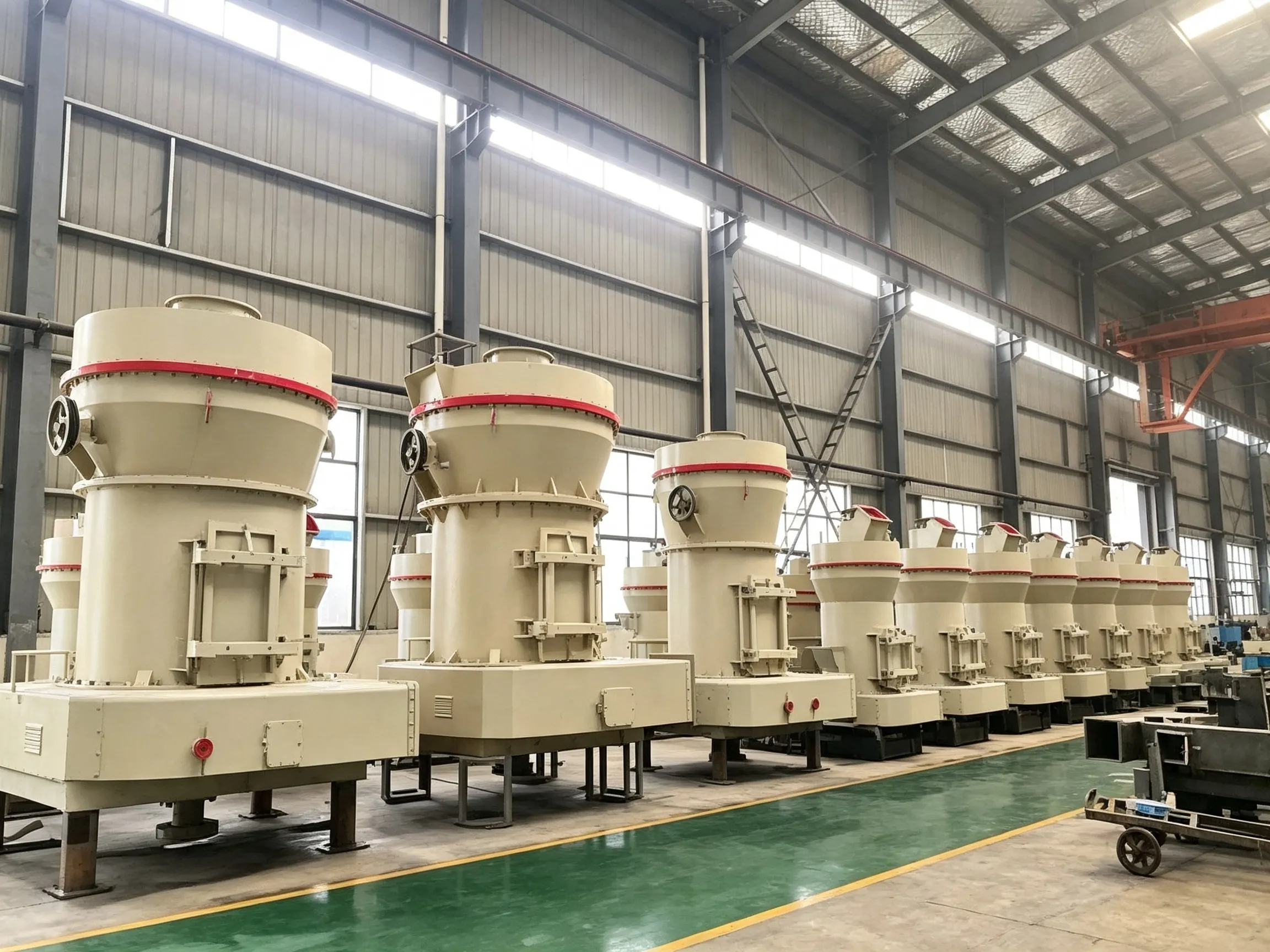
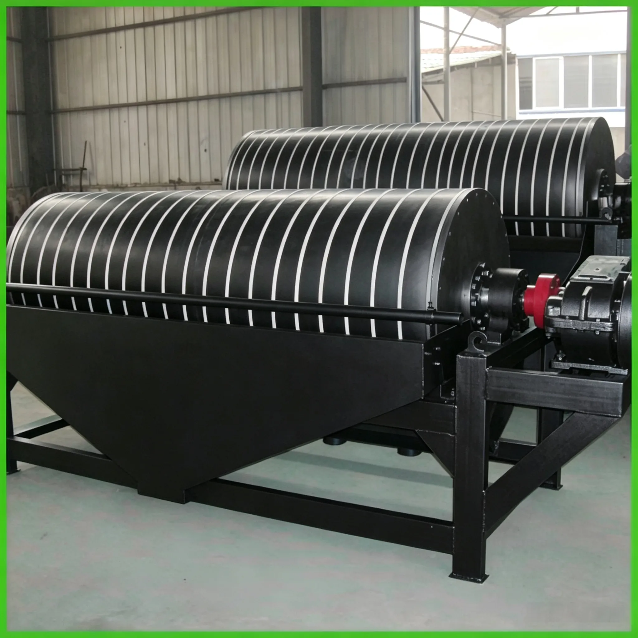

Permanent magnetic drum separators are widely used for magnetite ore beneficiation, coarse particle pre‑concentration and tailings discarding, concentration before filtration, recovery of magnetic heavy media, pre‑concentration for wet high‑intensity magnetic separation feed, and iron removal and purification of non‑metallic minerals such as quartz sand, depending on variations in magnetic field intensity, magnetic system arrangement, and drum structure.
Permanent magnetic drum separators are widely used for magnetite ore beneficiation, coarse particle pre‑concentration and tailings discarding, concentration before filtration, recovery of magnetic heavy media, pre‑concentration for wet high‑intensity magnetic separation feed, and iron removal and purification of non‑metallic minerals such as quartz sand, depending on variations in magnetic field intensity, magnetic system arrangement, and drum structure.
A permanent magnetic drum separator consists of a magnetic system, a drum, a separating tank, a drive device, and feed, discharge, and overflow devices. The arrangement of the magnetic system and the number of magnetic poles have a decisive influence on the separation performance. Depending on the drum diameter, the number of magnetic poles generally ranges from 4 to 7, with polarities alternating around the periphery. The drum is used to attract and transport magnetic particles and to prevent the slurry from penetrating into the magnetic system. The drum and its end covers are made of non‑magnetic materials with high electrical resistivity and corrosion resistance. The separating tank is generally made of austenitic stainless steel and lined with rubber or synthetic materials to prevent wear. The drum is typically driven by a geared motor or a Y‑series motor through a reducer.
Permanent magnet blocks are commonly made from strontium ferrite and barium ferrite materials. In recent years, rare‑earth permanent magnet materials such as neodymium‑iron‑boron (NdFeB) magnetic steel have also been adopted for magnet blocks; although the latter are more expensive, they offer excellent magnetic properties and require smaller quantities. At present, composite magnetic systems combining ferrite permanent magnet blocks and rare‑earth permanent magnet blocks are commonly used, which significantly improve separator performance (e.g., more than doubling the magnetic field intensity) and expand the application range of the separators. In recent years, magnetic systems composed entirely of rare‑earth permanent magnet blocks have been employed to achieve even higher magnetic field intensities and performance, as exemplified by the NCT series full‑rare‑earth permanent magnetic drum separators.
Depending on the operating mode, permanent magnetic drum separators are available in three tank configurations, as shown in Fig. 13‑2, namely: concurrent type (S), counter‑current type (N), and semi‑counter‑current type (B).
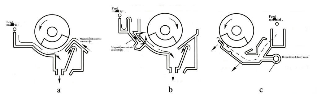
Fig. 13‑2 Three tank configurations of drum magnetic separators
(a) Concurrent type; (b) Semi‑counter‑current type; (c) Counter‑current type
The concurrent magnetic separator is suitable for ores larger than 6 mm; the counter‑current type is suitable for ores smaller than 2–3 mm; and the semi‑counter‑current type is suitable for ores smaller than 0.3 mm. When the magnetite content in the feed is low, i.e., when the tailings yield exceeds 50%, the three tank types give similar metallurgical performance. When the magnetic iron content in the feed is high, i.e., when the tailings yield is less than 30%, the concurrent type significantly outperforms the counter‑current and semi‑counter‑current types. In actual production, the appropriate tank configuration can be selected based on ore characteristics and the beneficiation process flowsheet.
Except for the notable differences in tank design, the other components of permanent magnetic drum separators are essentially similar to those of conventional magnetic separators. Fig. 13‑3 shows the construction of a semi‑counter‑current drum magnetic separator.

Fig. 13‑3 Structure of the permanent magnetic drum separator (semi‑counter‑current type)
1—Drum; 2—Magnetic system; 3—Tank; 4—Magnetic conductor plate; 5—Support; 6—Water spray pipe; 7—Feed box; 8—Ore discharge water pipe; 9—Base plate; 10—Magnetic declination adjustment device; 11—Bracket.
There are many manufacturers of permanent magnetic drum separators in China. Each, based on its own expertise, has made improvements and adjustments to varying degrees in terms of the magnetic circuit, field intensity, gradient, number of poles, wrap angle, depth of magnetic field action, and pole materials of the magnetic system, as well as the drive system, bearing arrangement and configuration, and tank structure. As a result, a wide variety of series and a complex range of models and specifications exist. However, the basic dimensions—drum diameter and drum length—have remained unchanged. Therefore, the series, models, specifications, and technical parameters of the permanent magnetic drum separators that are currently mainstream and widely used in China are listed in Table 13‑1.
Table 13‑1 Technical parameters of the BX type permanent magnetic drum separator
| model | Simplified size (D×L) /mm×mm | Surface field strength/0e① | processing power | Motor power / kW | Cylinder rotational speed /r ·min⁻¹ | Weight | |
| /1 ·h⁻¹ | /m³ ·h-¹ | ||||||
| CTS/CTN/CTB-44 | 400×400 | 1000~8000 | 1~2 | 3 | 1.1 | 45 | 350 |
| CTS/CTN/CTB-46 | 400×600 | 1000~8000 | 1-3 | 5 | 1.1 | 45 | 600 |
| CTS/CTN/CTB-63 | 600×300 | 1000~8000 | 3~5 | 8 | 1.1 | 40 | 600 |
| CTSCTV/CTB-66 | 600×600 | 1000~8000 | 5~10 | 16 | 1.1 | 40 | 750 |
| CTSCTN/CTB-69 | 600×900 | 1000-8000 | 8-15 | 24 | 1.1 | 40 | 780 |
| CTSCTVCTB-612 | 600×1200 | 1000~8000 | 10~20 | 32 | 2.2 | 40 | 990 |
| CTS/CTV/CTB-618 | 600×1800 | 1000-8000 | 15~30 | 48 | 2.2 | 40 | 1330 |
| CTS/CTNCTB-712 | 750×1200 | 1000~8000 | 15-30 | 48 | 3 | 35 | 1500 |
| CTSCTN/CTB-718 | 750×1800 | 1000-8000 | 20~45 | 72 | 3 | 35 | 2100 |
Continued Table 13=1
| model | Cylinder size (D×L) /mm×mm | Surface field strength/0e① | processing power | electric motorpower/kW | Cylinder rotational speed /r ·min⁻¹ | Weight | |
| /t ·h⁻¹ | /m³ ·h-¹ | ||||||
| CTS/CTNCTB-918 | 900×1800 | 1000~8000 | 25-55 | 90 | 4 | 28 | 2500 |
| CTS/CTN/CTB-924 | 900×2400 | 1000~8000 | 35~70 | 110 | 4 | 28 | 2500 |
| CTS/CTN/CTB-1018 | 1050×1800 | 1000-8000 | 40-75 | 120 | 5.5 | 22 | 4000 |
| CTS/CTN/CTB-1021 | 1050×2100 | 1000~8000 | 45~88 | 140 | 5.5 | 22 | 4500 |
| CTS/CTN/CTB-1024 | 1050×2400 | 1000-8000 | 52-100 | 160 | 5.5 | 22 | 5000 |
| CTS/CTN/CTB-1030 | 1050×3000 | 1000~8000 | 65~125 | 200 | 7.5 | 19 | 5800 |
| CTS/CTN/CTB-1218 | 1200×1800 | 1000~8000 | 47-90 | 140 | 5.5 | 19 | 6200 |
| CTS/CTN/CTB-1224 | 1200×2400 | 1000~8000 | 52~100 | 160 | 5.5 | 19 | 6200 |
| CTS/CTN/CTB-1230 | 1200×3000 | 1000~8000 | 82~120 | 192 | 7.5 | 19 | 7200 |
| CTS/CTN/CTB-1530 | 1500×3000 | 1000-8000 | 90-170 | 270 | 11 | 14 | |
| CTS/CTN/CTB-1540 | 1500×4000 | 1000-8000 | 115-220 | 350 | 11 | 14 | |
①10e=79.58A/m.
Main Operating Parameters of Permanent Magnetic Drum Separators
In actual production, the main parameters affecting the process performance of permanent magnetic drum separators include: drum rotational speed, magnetic pole offset angle, working gap, gap at the concentrate discharge, and throughput. To date, there is no precise calculation method for these parameters, and the only approach is to continuously explore and test them during production practice to determine the most suitable operating parameters.
13.2.2.1 Drum rotational speed
The drum rotational speed directly affects the centrifugal force on the mineral particles on the drum surface. When the rotational speed increases, some locked particles with weaker magnetic attraction are discharged into the tailings, which tends to raise both the concentrate grade and the tailings grade, while iron recovery decreases slightly, though the changes are not very pronounced. Considering the improvement in concentrate quality and throughput, the change in drum rotational speed should be moderate.
13.2.2.2 Magnetic pole offset angle
The magnetic pole offset angle directly affects the width of the scavenging zone. As the offset angle increases, the scavenging zone narrows, and the scavenging time shortens. This results in a slight increase in both concentrate grade and tailings grade, and a decreasing trend in iron recovery, but the changes are relatively small, and satisfactory metallurgical performance can still be achieved. For most permanent magnetic drum separators manufactured in China, the magnetic system is well‑designed with a rational magnetic circuit, and the offset angle can be adjusted within a wide range of 5° to 25° according to the properties of different ores.
13.2.2.3 Working gap
The working gap refers to the minimum cross‑sectional area between the drum and the bottom plate of the tank in the scavenging zone through which the slurry can pass, and is conventionally expressed as the height of the cross‑section. This gap determines the processing capacity of the separator: a larger gap increases throughput but leads to higher tailings losses; conversely, a smaller gap reduces throughput and affects production. Depending on the specific conditions, this gap is generally set between 35 and 60 mm.
13.2.2.4 Gap at concentrate discharge
The gap at the concentrate discharge is determined by the production capacity. An inappropriate size affects ore discharge: if too large, the tailings grade increases and processing capacity decreases; if too small, concentrate discharge becomes difficult. Based on the amount of concentrate, this gap is usually 15 to 25 mm, with a typical value of 20 mm.
13.2.2.5 Throughput
The throughput of a permanent magnetic drum separator can be selected based on actual production data, or estimated by the unit capacity per meter of drum length, using the following calculation formula (Equation 13‑1):
Q = K · q · L (13-1)
Where:
Q — dry ore throughput of the magnetic separator, t/h;
K — coefficient, generally taken as 0.85;
q — throughput per meter of drum length, t/(m·h);
L — drum length, m.
Installation and Trial Operation of Permanent Magnetic Drum Separators
13.2.3.1 Installation of Permanent Magnetic Drum Separators
The details are as follows:
(1) During installation, care should be taken to handle the equipment gently, keep it away from iron objects, avoid impacts, and prevent deformation.
(2) The clearance *a* between the drum and the tank, and the clearance *b* between the drum and the discharge opening must conform to the specifications stipulated in the design documents (see Fig. 13‑4).

Fig. 13‑4 Drum magnetic separator
1—Feed opening; 2—Drum; 3—Magnetic system; 4—Ore washing water pipe; 5—Discharge opening; 6—Overflow weir; 7—Adjustable tailings outlet; 8—Overflow port;
a—Clearance between the drum and the tank;
b—Clearance between the drum and the discharge opening;
α—Adjustment angle for the magnetic system position.
(3) The permissible deviations for the installation of the drum magnetic separator and the inspection methods shall comply with the provisions specified in Table 13‑2.
13.2.3.2 Trial operation of the permanent magnetic drum separator
The trial operation of the permanent magnetic drum separator shall meet the following requirements:
(1) The no‑load trial operation shall last no less than 2 hours.
(2) Before trial operation, the tank body and any adhering materials must be thoroughly cleaned.
(3) The drive mechanism shall operate without jamming or abnormal noise.
(4) All fasteners and connecting parts shall not be loose.
(5) The temperature of lubricated bearings shall not exceed 70 °C, and that of rolling bearings shall not exceed 80 °C.
Table 13‑2 Permissible deviations for installation of drum magnetic separators
| Item No. | Item | Permissible deviation | Unit | Inspection method |
|---|---|---|---|---|
| 1 | Longitudinal and transverse center lines | 3.0 | mm | Check by pulling a wire and measuring |
| 2 | Drum elevation | ±5.0 | mm | Check with a steel ruler or level |
| 3 | Drum levelness | 0.3/1000 | — | Check with a level |
| 4 | Full‑length height difference of the overflow weir | ±2.0 | mm | Check with a level |
13.2.4 Operation of permanent magnetic drum separators
13.2.4.1 Start‑up and shut‑down
The start‑up and shut‑down procedures are as follows:
(1) Pre‑start inspection. Check whether the equipment is in good condition, whether all bolts are tight, whether there are any obstructions in the transmission parts, and carry out hand‑turning for 2–3 revolutions before starting.
(2) Start‑up sequence. Start the equipment in the order from the downstream to the upstream according to the process flow. After the separator tank is filled with clean water, start the motor and then feed the ore.
(3) Shut‑down sequence. The shut‑down sequence is the reverse of the start‑up sequence, i.e., from upstream to downstream.
13.2.4.2 Operation
The operation requirements are as follows:
(1) Regularly check the wear of the drum shell. If the wear‑resistant layer is worn or detached, it should be repaired or replaced promptly.
(2) If any iron pieces or debris fall into the tank, they must be removed immediately.
(3) The temperature rise of bearings and motors should generally not exceed 70 °C.
(4) The drive chain should have proper tension; replace the chain promptly when severe wear occurs.
(5) All lubrication points must have sufficient grease.
(6) The water pressure at each water pipe should not be less than 0.12 MPa.
13.2.5 Maintenance of permanent magnetic drum separators
13.2.5.1 Maintenance contents
The structure of the permanent magnetic drum separator is simple. Maintenance is generally carried out based on the degree of wear and damage observed.
13.2.5.2 Maintenance methods
The maintenance methods are as follows:
(1) Magnetic system. The magnetic system is the most important component of the separator, consisting of the main shaft connecting plate, yoke plates, and magnet blocks. The magnet blocks are made of Y30BH strontium ferrite material and fixed on the yoke plates. The entire magnetic system is encapsulated and protected with 1Cr18Ni9Ti stainless steel to prevent the magnet blocks from falling off or being damaged. However, due to long‑term operation, magnet blocks may still crack. In such cases, the entire set should be removed and replaced with a new one, rather than replacing only the broken block.
(2) Drum. The drum of the permanent magnetic drum separator is generally made of 3–5 mm thick 1Cr18Ni9Ti stainless steel plate, depending on the drum diameter. The protection of the drum greatly affects the service life of the separator. To prevent wear, manufacturers cover the drum surface with a highly wear‑resistant fabric‑reinforced rubber sheet, 6 mm thick, of which the bottom layer (2 mm) is bonded to the stainless steel drum with an adhesive layer, and the outer layer (4 mm) is wear‑resistant rubber. During production, if local wear is found on the rubber sheet, it should be repaired promptly with rubber patching. If wear is severe, the entire sheet should be replaced.
(3) Tank. The tank is made of 1Cr18Ni9Ti stainless steel plate, welded by argon arc welding or CO₂ shielded welding to ensure the quality of the weld and to prevent leakage during operation. The bottom of the tank has an arc‑shaped structure to avoid material accumulation and to reduce impact on the tank bottom. The shape and dimensions of the tank directly affect the separation performance; therefore, during operation and maintenance, its shape, dimensions, and wear condition should be strictly inspected, and any problems should be promptly repaired.
(4) Transmission parts. The transmission of the permanent magnetic drum separator consists of a geared motor and a roller chain drive. The drive motor is equipped with an overcurrent protector, so major problems are unlikely during production. In long‑term operation, the roller chain tends to elongate and should be repaired or replaced in a timely m
 English English
 Spanish
 Russian
 Arabic
 Swahili
 French
 Turkish
 Portuguese
 Korean
 Japanese
 German
 Italian