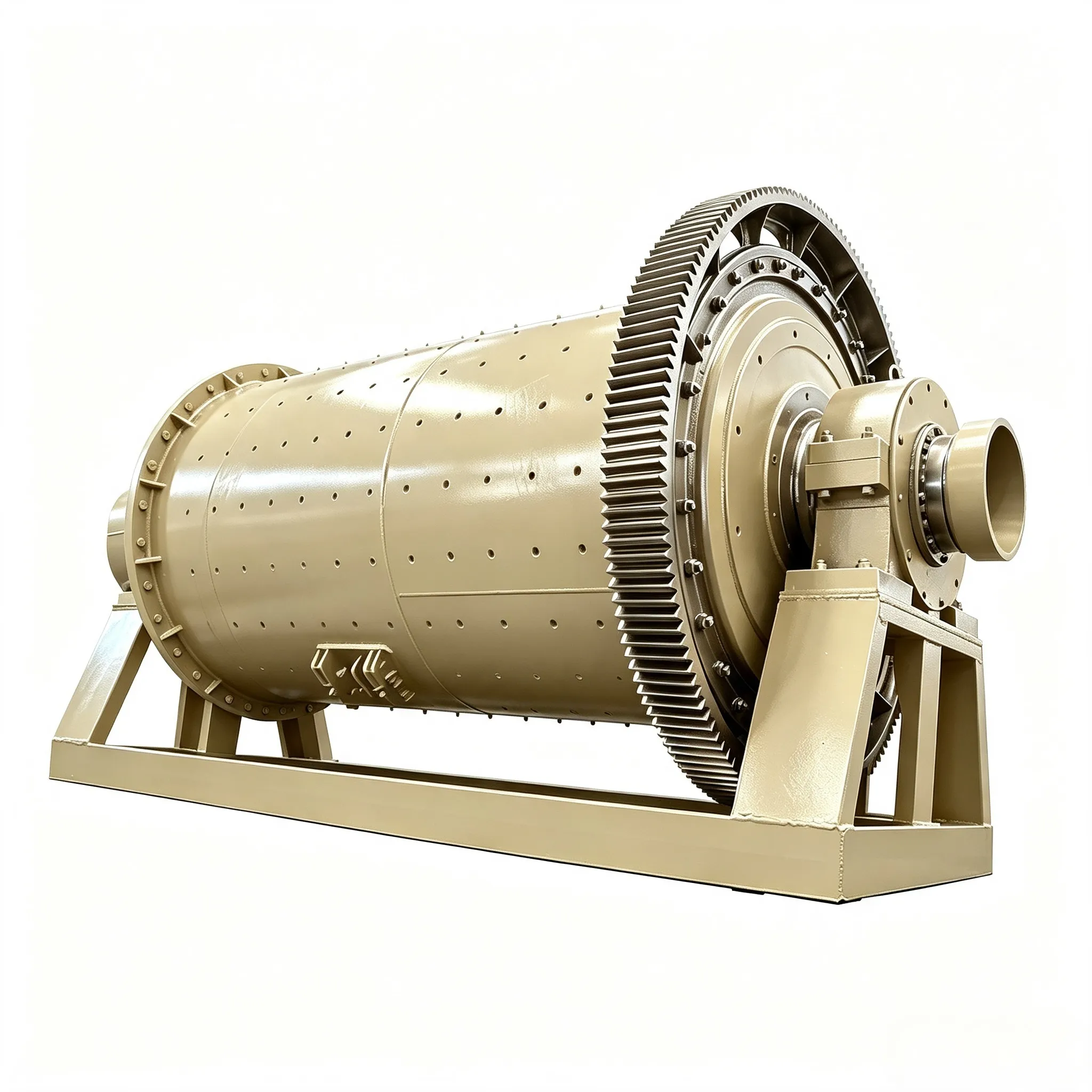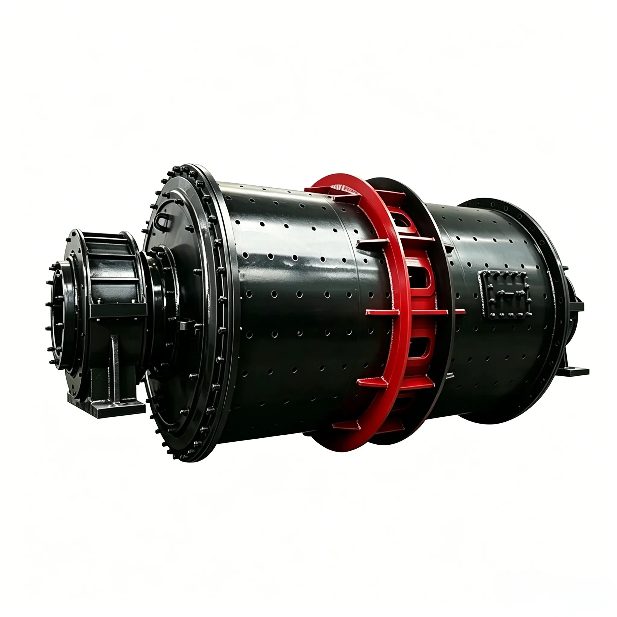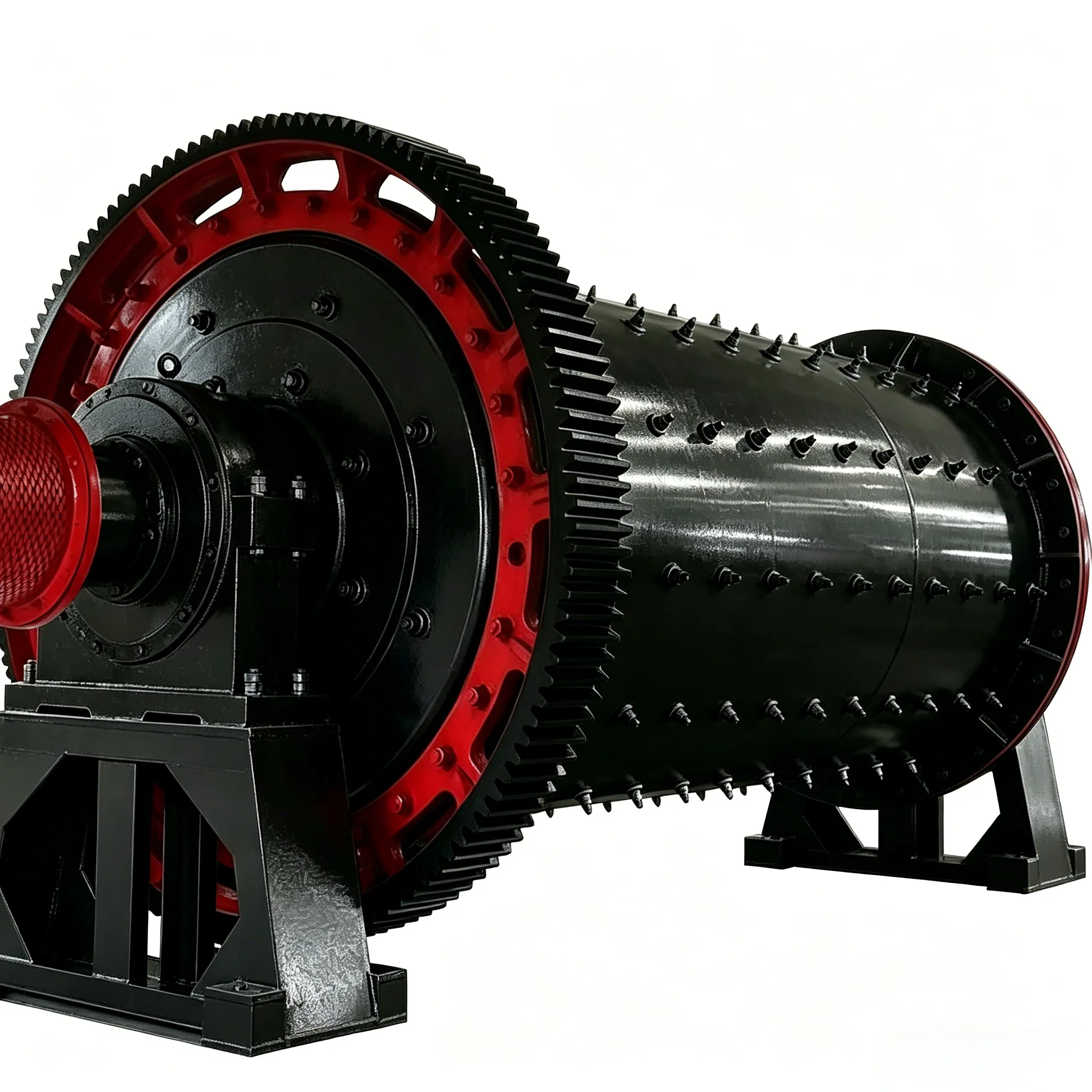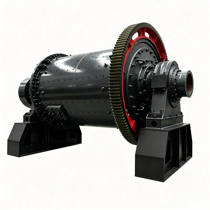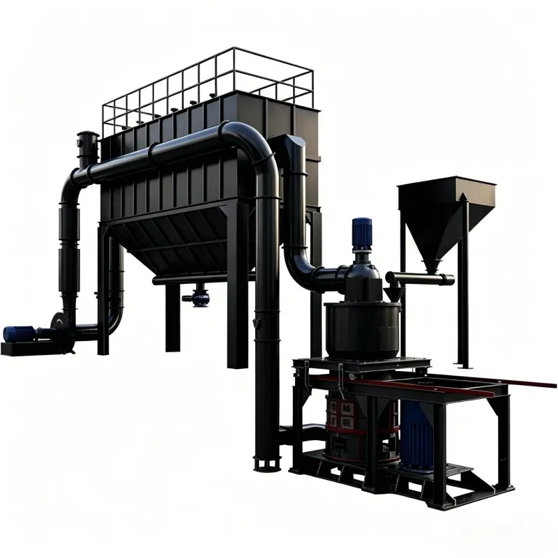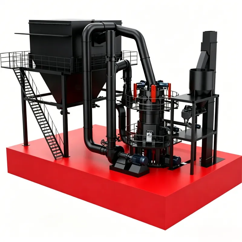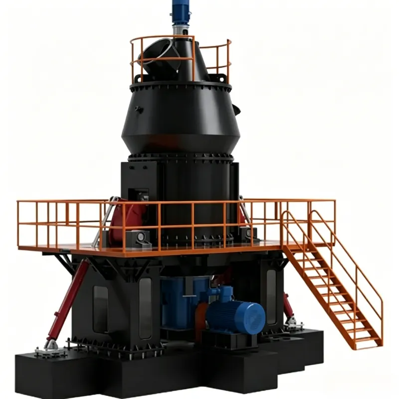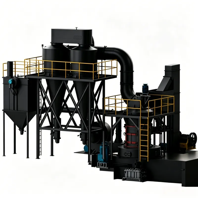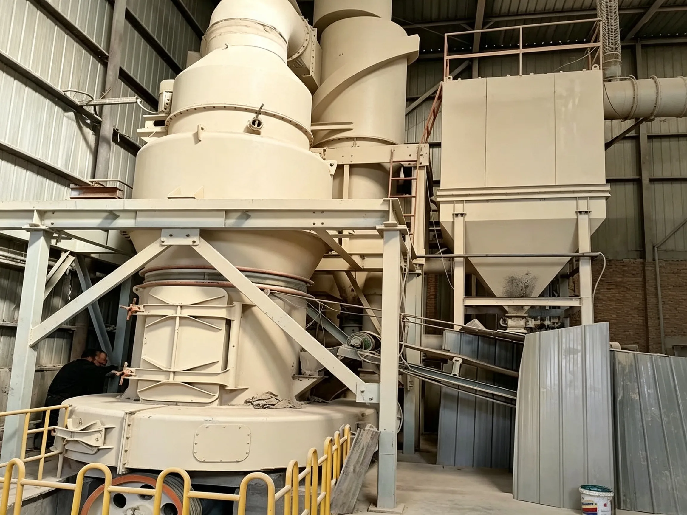

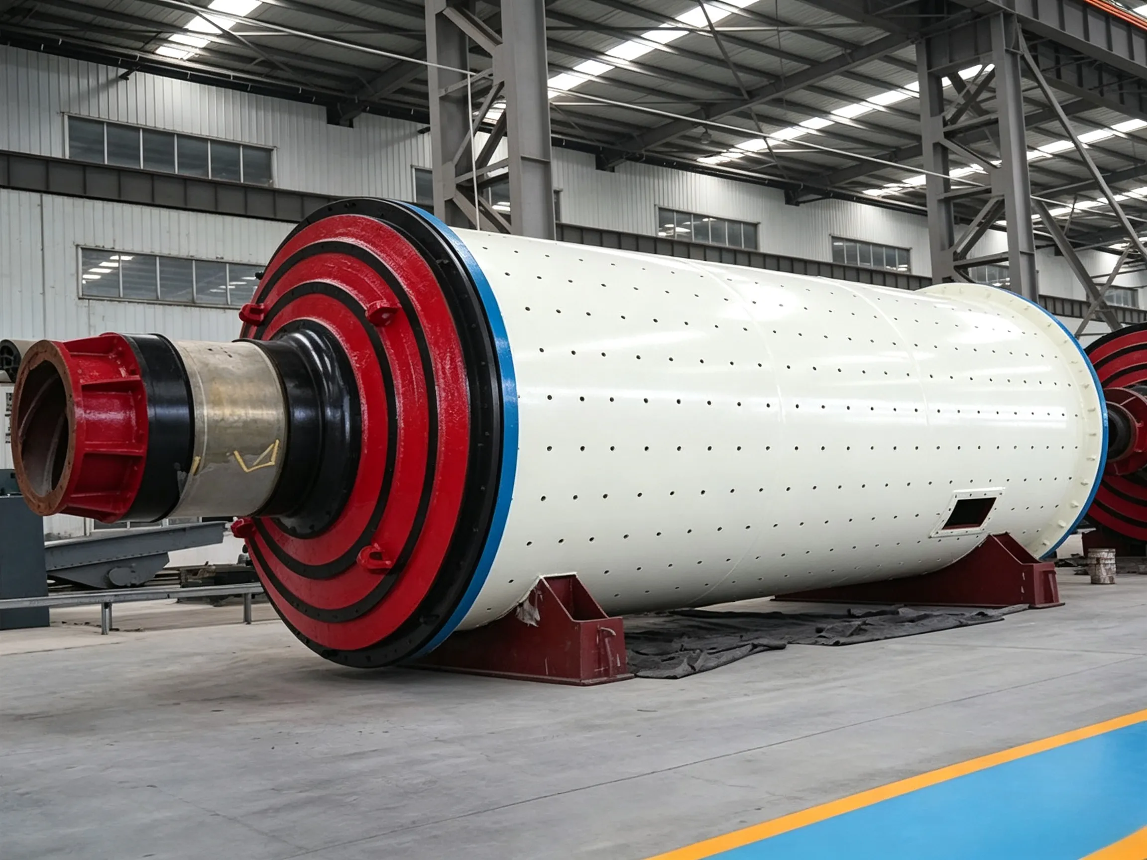
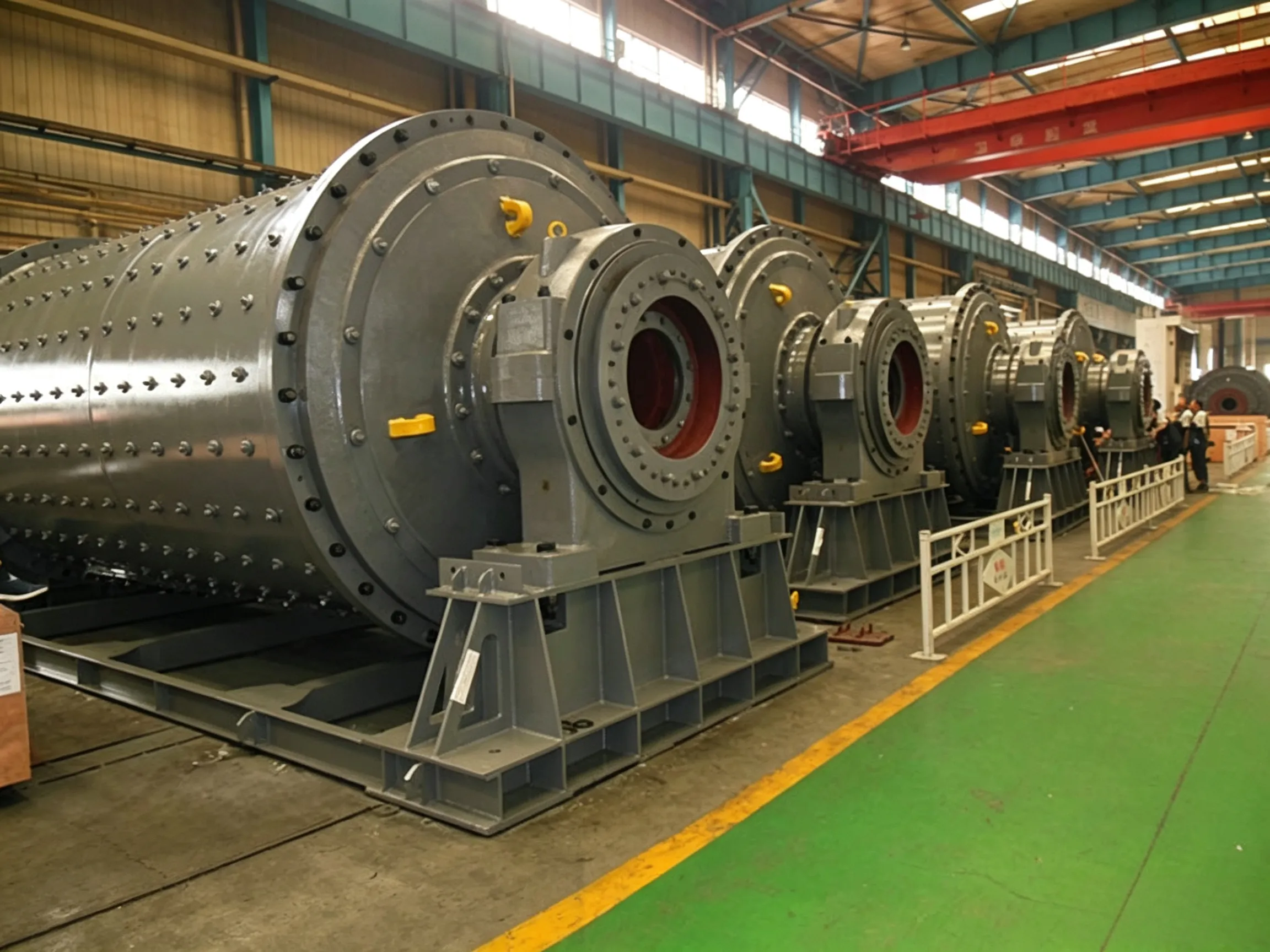







The rotary dryer, also known as a drum dryer, is a continuous industrial drying device based on a rotating cylindrical shell. It is primarily used for dewatering bulk materials in industrial and agricultural applications. Through co-current or counter-current heat exchange, the rotating drum drives internal lifting plates (flights) to continuously lift and shower the material, increasing the contact area between the material and the hot gas stream, thus achieving efficient drying.
Rotary dryers are widely used in building materials, metallurgy, chemical engineering, and mineral processing industries. They are suitable for drying blast‑furnace slag, clay, quartz stone, pulverised coal, sand, limestone, and other bulk materials. In metal ore processing plants, they are used for drying various metal concentrates; in steel mills, they dry cleaned coal, fluorite, iron oxide scale, etc. The operating temperature generally ranges from 400 °C to 800 °C.
Key advantages: large processing capacity, stable operation, low energy consumption, easy operation, and strong adaptability to different materials.
The rotary dryer consists mainly of the following components:
| No. | Component | Function |
|---|---|---|
| 1 | Shell (drum) | Main container for material drying |
| 2 | Front/ rear riding rings | Support the rotating drum |
| 3 | Girth gear / pinion | Transmit drive power |
| 4 | Thrust rollers / carrying rollers | Support and position the drum |
| 5 | Lifting plates (flights) | Lift and shower material to increase heat‑exchange area |
| 6 | Reducer / motor | Drive system |
| 7 | Hot air duct / feed chute | Hot gas supply and material feed |
| 8 | Furnace | Heat source |
Optional auxiliary equipment can be supplied according to user requirements, including gas generators, combustion chambers, bucket elevators, belt conveyors, weigh feeders, cyclone dust collectors, induced‑draft fans, etc.
Wet material is fed by a belt conveyor or bucket elevator into the feed hopper, then enters the drying end through the feed pipe. The dryer shell is inclined at a slight angle to the horizontal (typically 3°–5°). Material is introduced at the higher end and moves towards the lower end under gravity as the drum rotates.
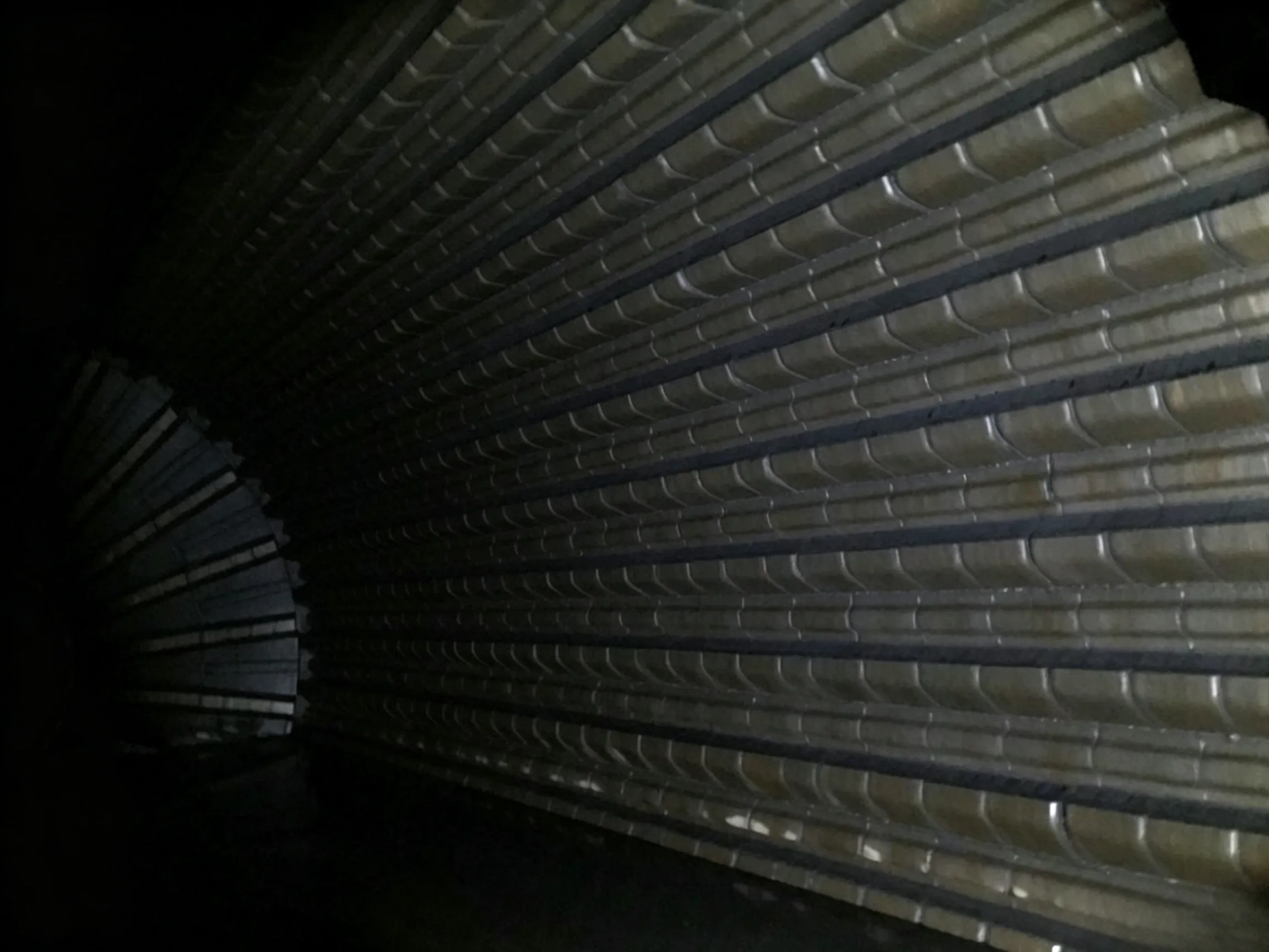
Lifting plates (flights) mounted on the inner wall of the shell lift the material and shower it down, creating a dense material curtain that comes into full contact with the hot gas stream. This maximises the heat‑transfer area and improves drying efficiency. The heating medium (hot air or flue gas) can be arranged in co‑current or counter‑current flow depending on the process requirements. As the wet material moves forward inside the drum, it receives heat directly or indirectly from the heating medium, completing the drying process. The dried material is discharged at the outlet via a belt conveyor or screw conveyor. The heating medium, after passing through the dryer, is generally cleaned by a cyclone dust collector; when necessary, a bag filter or wet scrubber can be added before final discharge.
| Type | Heat‑Transfer Mode | Application |
|---|---|---|
| Direct heating | Hot gas directly contacts the material | Materials that are not sensitive to high temperature or dust contamination |
| Indirect heating | Hot gas heats a metal jacket which then transfers heat indirectly | Materials that are sensitive to hot gas or dust contamination |
| Compound heating | Indirect heating inside an inner sleeve + direct heating outside the sleeve | Materials prone to ignition/explosion or that cannot contact high‑temperature gas |
| Type | Characteristic | Application |
|---|---|---|
| Co‑current | Material and hot gas flow in the same direction; rapid heat exchange | Materials with high initial moisture and moderate final moisture requirements |
| Counter‑current | Material and hot gas flow in opposite directions; even drying | Materials with low initial moisture and strict final moisture requirements |
The following table lists technical parameters for mainstream rotary dryer models:
| Model (mm) | Shell Dia. (mm) | Shell Length (mm) | Slope (%) | Speed (r/min) | Inlet Temp. (℃) | Power (kW) | Weight (t) | Capacity (t/h) |
|---|---|---|---|---|---|---|---|---|
| Φ600×6000 | 600 | 6000 | 3 | 3.8 | ≤700 | 4 | 2.9 | 0.5–1.5 |
| Φ800×8000 | 800 | 8000 | 5 | 3.8 | ≤700 | 4 | 3.5 | 0.8–2.0 |
| Φ1000×9000 | 1000 | 9000 | 5 | 3.8 | ≤700 | 4 | 5.2 | 0.8–2.5 |
| Φ1000×10000 | 1000 | 10000 | 5.3 | 3 | ≤700 | 5.5 | 5.6 | 1.0–3.5 |
| Φ1200×10000 | 1200 | 10000 | 3.5 | 3 | ≤700 | 7.5 | 14.0 | 1.8–5.0 |
| Φ1200×12000 | 1200 | 12000 | 3.5 | 3 | ≤700 | 11 | 14.8 | 2.0–6.0 |
| Φ1500×12000 | 1500 | 12000 | 3.5 | 2.08 | ≤800 | 15 | 17.8 | 3.3–7.5 |
| Φ1800×12000 | 1800 | 12000 | 3.5 | 2.08 | ≤800 | 18 | 25 | 5.0–9.0 |
| Φ2000×18000 | 2000 | 18000 | 3–5 | 1.5–6 | ≤800 | 18.5 | — | 7.0–15 |
| Φ2200×12000 | 2200 | 12000 | 3.5 | 4.7 | ≤700 | 18.5 | 33 | 6.0–12 |
| Φ2200×18000 | 2200 | 18000 | 3.5 | 4 | ≤800 | 30 | 53.3 | 10–15 |
| Φ2200×20000 | 2200 | 20000 | 3.5 | 4 | ≤800 | 35 | 56 | 12–20 |
| Φ2400×20000 | 2400 | 20000 | 3.5 | 4 | ≤800 | 37 | 60 | 18–25 |
| Φ3000×20000 | 3000 | 20000 | 3.5 | 4 | ≤800 | 55 | 78 | 25 |
| Φ3000×25000 | 3000 | 25000 | 3.5 | 4 | ≤800 | 75 | 104.9 | 32–36 |
| Model | Shell Dia. (m) | Shell Length (m) | Slope (%) | Inlet Temp. (℃) | Speed (r/min) | Flow Type | Motor Power (kW) |
|---|---|---|---|---|---|---|---|
| NHH1512 | 1.5 | 12 | 5 | 800 | 2.08 | Co‑current | 18.5 |
| NHH1512A | 1.5 | 12 | 5 | 800 | 4.089 | Co‑current | 15 |
| NHH2212 | 2.2 | 12 | 3 | 650 | 3.77 | — | 30 |
| NHH2420 | 2.4 | 20 | 6 | — | 2.31 | Counter‑current | 45 |
| NHH3020 | 3.0 | 20 | 3 | — | 3.5 | Co‑current | 55 |
| Model (m) | Diameter (mm) | Length (mm) | Capacity (t/h) | Speed (r/min) | Slope (%) | Motor Power (kW) | Weight (t) |
|---|---|---|---|---|---|---|---|
| Φ1.5×12 | 1500 | 12000 | 6–9 | 1.4–7 | 5 | 15 | 18.6 |
| Φ1.5×14 | 1500 | 14000 | 7–10 | 1.4–7 | 5 | 15 | 17.9 |
| Φ1.6×14 | 1600 | 14000 | 8–11 | 1.4–7 | 5 | 15 | 18.6 |
| Φ1.8×14 | 1800 | 14000 | 9–13 | 3.5–6.5 | 5 | 15 | 20.85 |
| Φ2.0×14 | 2000 | 14000 | 11–16 | 2.2–7.4 | 5 | 18.5 | 23.2 |
| Φ2.2×12 | 2200 | 12000 | 12–17 | 2.2–7.4 | 5 | 22 | 30.3 |
| Φ2.2×14 | 2200 | 14000 | 14–20 | 2.2–7.4 | 5 | 22 | 32.23 |
| Φ2.4×18 | 2400 | 18000 | 21–31 | 2.2–7.4 | 4 | 30 | 54 |
| Φ2.4×20 | 2400 | 20000 | 23–34 | 2.2–7.4 | 4 | 37 | 56 |
| Φ2.4×22 | 2400 | 22000 | 26–38 | 2.2–7.4 | 4 | 37 | 58 |
| Φ2.6×20 | 2600 | 20000 | 28–40 | 2.2–7.4 | 4 | 45 | 60.5 |
| Φ2.6×24 | 2600 | 24000 | 33–48 | 2.2–7.4 | 4 | 45 | 72.7 |
| Φ3.0×20 | 3000 | 20000 | 35–54 | 8.4–3.85 | 4 | 55 | 86 |
| Φ3.0×25 | 3000 | 25000 | 46–64 | 8.4–3.85 | 4 | 75 | 96 |
| Φ3.0×28 | 3000 | 28000 | 52–74 | 8.4–3.85 | 4 | 75 | 122 |
| Φ3.2×25 | 3200 | 25000 | 60–80 | 2.4–7.6 | 4 | 90 | 119 |
| Model | Capacity (t/h) | Power (kW) | Drum Speed (r/min) | Weight (t) |
|---|---|---|---|---|
| Φ0.6×8 m | 1.5–2.8 | 4 | 8 | 5.1 |
| Φ0.8×10 m | 3.0 | 4 | 7.5 | 6.9 |
| Φ1.0×10 m | 3.3–4.9 | 5.5 | 5.8 | 7.5 |
| Φ1.2×10 m | 4–6 | 7.5 | 4.8 | 13.5 |
| Φ1.5×12 m | 4–6 | 10 | 4.8 | 18.9 |
| Φ1.5×15 m | 7–12 | 18.5 | 4.8 | 21 |
| Φ1.8×12 m | 7–12 | 18.5 | 4.1 | 22.83 |
| Φ2.2×12 m | 12 | 18.5 | 3.2 | 37.6 |
| Φ2.2×14 m | 12 | 22 | 3.2 | 40 |
| Φ2.2×16 m | 10–13 | 30 | 3.2 | 45 |
| Φ2.4×14 m | 10–14 | 30 | 3 | 51 |
| Φ2.4×18 m | 25 | 37 | 3 | 54 |
| Φ2.4×20 m | 32–36 | 37 | 3 | 54.14 |
| Φ3×20 m | 40–50 | 55 | 2.59 | 78 |
| Φ3×25 m | 45–58 | 75 | 2.59 | 104.9 |
| Required Capacity | Recommended Model | Motor Power |
|---|---|---|
| < 3 t/h | Φ1200×10000 or smaller | ≤ 7.5 kW |
| 3–10 t/h | Φ1500×12000 – Φ1800×12000 | 15–18 kW |
| 10–20 t/h | Φ2200×12000 – Φ2200×20000 | 18.5–35 kW |
| 20–35 t/h | Φ2400×20000 – Φ3000×20000 | 37–55 kW |
| > 35 t/h | Φ3000×25000 or larger | ≥ 75 kW |
Rotary dryers are widely used in the following industries:
 English English
 Spanish
 Russian
 Arabic
 Swahili
 French
 Turkish
 Portuguese
 Korean
 Japanese
 German
 Italian