



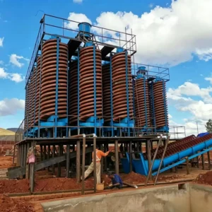
The spiral chute is a gravity concentration device that utilises the inertial centrifugal force generated during the spiral rotary motion of the pulp to separate heavy and light minerals. It combines the advantages of various equipment such as spiral concentrators
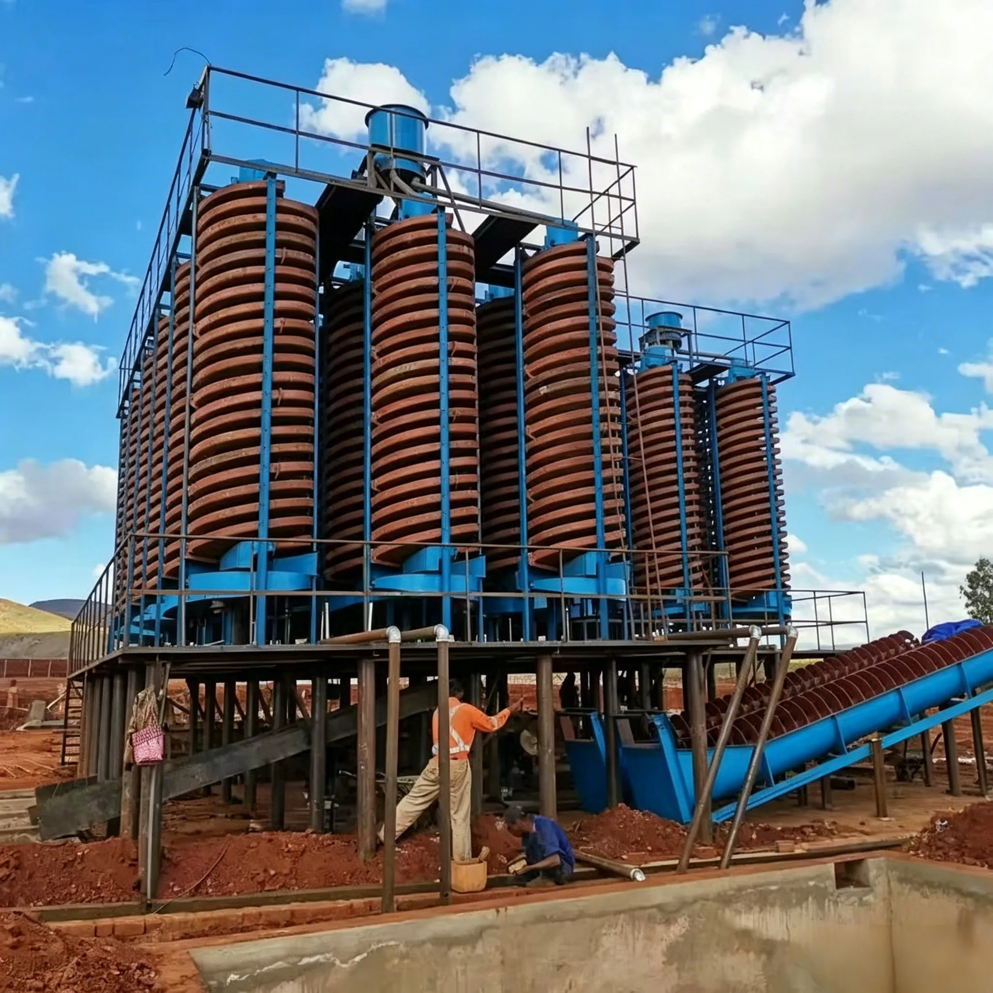
The spiral chute is a gravity concentration device that utilises the inertial centrifugal force generated during the spiral rotary motion of the pulp to separate heavy and light minerals. It combines the advantages of various equipment such as spiral concentrators, shaking tables, and centrifugal concentrators, making it an ideal piece of equipment for mining and mineral processing, particularly suited for alluvial mining along seashores, riverbanks, sand beaches, and stream channels.
The spiral chute features outstanding advantages including simple structure, light weight, no power requirement, water and energy savings, easy operation and maintenance, strong adaptability, fine separation size, large throughput, and excellent separation performance. It is widely used in both pre‑concentration and cleaning stages for heavy minerals. This equipment was once appraised and approved by China’s Ministry of Metallurgy in conjunction with relevant research institutes, design units, universities, and mining enterprises, and was confirmed to have good performance and advanced separation indices, leading to batch production and widespread promotion.
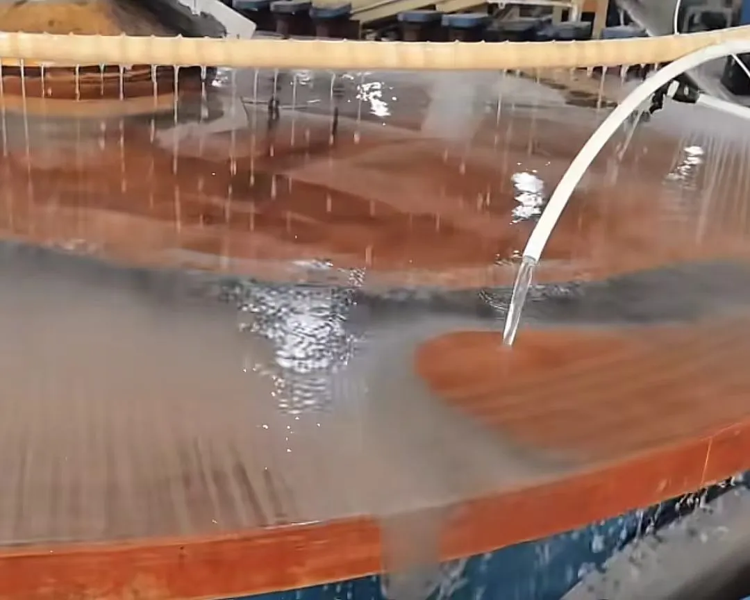
The separation process of the spiral chute belongs to inclined‑flow separation. Pulp is pumped to the two feed inlets at the top of the spiral chute, where supplementary water is added to adjust the pulp density. The pulp then flows naturally downward along the spiral trough under the action of gravity. During this process, the particles are subjected to the combined effects of the following forces:
Because the velocity distribution in the flowing water is higher in the upper layer and lower in the lower layer, high‑density particles concentrate in the lower layer. Under the combined action of water drag and greater bottom friction, they move slowly along the trough bottom; low‑density particles concentrate in the upper layer and are carried away more rapidly by the water flow. Eventually, minerals of different densities form distinct bands of varying grades along the trough, and the concentrate, middlings, and tailings are respectively collected by the splitting device at the discharge end.
No wash water is added during the entire separation process; separation relies entirely on the self‑flow of the pulp and the combined effects of gravity and centrifugal force.
The spiral chute mainly consists of the following six to eight components:
| No. | Component | Function |
|---|---|---|
| 1 | Feed distributor (splitter) | Pulp distribution device located at the very top of the spiral trough; utilising the positive pressure of the pulp inside the cylinder, it evenly distributes pulp through peripheral discharge pipes to the feed chutes |
| 2 | Feed chute | Located between the distributor and the spiral trough; it buffers and stabilises the pulp before feeding it evenly into the spiral trough |
| 3 | Spiral trough | The main body where the separation process takes place |
| 4 | Product splitter (splitting chute) | Attached to the lower discharge end of the spiral trough to split concentrate, middlings, and tailings |
| 5 | Collecting launder (product collection tank) | A concentric annular cylinder that gathers the split products by type and directs them to the next operation |
| 6 | Steel support stand (cross frame/tripod) | Supports the entire equipment, ensuring sufficient structural strength |
The spiral trough is the core component. Its cross‑section profile is a cubic parabola with the equation x = ay². This compound curved cross‑section provides the widest laminar flow zone, which is more favourable for the separation and recovery of fine particles.
Each spiral chute can be manufactured with different numbers of starts, i.e., single‑start, double‑start, triple‑start, and four‑start configurations. Each start is assembled from 4‑5 sections of spiral blades bolted together. The spiral blades are made of FRP (fibreglass‑reinforced plastic). The separation surface of the spiral trough has a special wear‑resistant layer, usually coated with polyurethane rubber or epoxy resin mixed with emery, offering advantages such as light weight, ruggedness, and long service life.
The product splitter is of a valve‑block design, using triangular valve blocks as adjustable splitting‑width elements, which are flexible, reliable, and easy to operate. The bottom slope of the collecting launder should be greater than 25% to ensure smooth discharge of concentrate, middlings, and tailings.
| Type | Feed Size | Description |
|---|---|---|
| Sand chute | Approximately 2‑3 mm | For conventional sand ores |
| Slime chute | Maximum <0.074 mm | For fine particles |
| Coarse chute | >2‑3 mm, up to 100‑200 mm | For coarse particles |
| Type | Characteristics | Application |
|---|---|---|
| Single‑start | Simplest structure, smallest throughput | Small/experimental use |
| Double‑start | Moderate throughput, stable separation | Small to medium concentrators |
| Triple‑start / four‑start | Large throughput, high efficiency | Large concentrators |
| Type | Characteristics |
|---|---|
| FRP spiral chute | Light weight, moisture‑proof, rust‑proof, corrosion‑resistant; integrally moulded in one piece |
| Polyurethane spiral chute | Superior wear resistance, acid/alkali resistant, low‑temperature resistant (‑30℃), anti‑ageing; longer service life |
| Model | 5LL‑1500 | 5LL‑1200 | 5LL‑900 | 5LL‑600 | 5LL‑400 |
|---|---|---|---|---|---|
| Outer diameter (mm) | 1500 | 1200 | 900 | 600 | 400 |
| Pitch (mm) | 540/720 | 900/720/540 | 675/540/405 | 450/360/270 | 240/180 |
| Pitch‑to‑diameter ratio | 0.75/0.6/0.45 | 0.75/0.6/0.45 | 0.75/0.6/0.45 | 0.75/0.6/0.45 | 0.6/0.45 |
| Transverse slope | 9° | 9° | 9° | 9° | 9° |
| Maximum number of starts | 4‑2 | 4‑2 | 4‑2 | 3 | 2 |
| Feed size (mm) | 0.3‑0.02 | 0.3‑0.03 | 0.3‑0.03 | 0.2‑0.02 | 0.2‑0.02 |
| Feed density (%) | 25‑55 | 25‑55 | 25‑55 | 25‑55 | 25‑55 |
| Capacity (t/h) | 6‑8 | 4‑6 | 2‑3 | 0.8‑1.2 | 0.15‑0.2 |
| Overall dimensions (mm) | 1560×1560×5230 | 1360×1360×5230 | 1060×1060×4000 | 700×700×2600 | 460×460×1500 |
| Weight (kg) | 800 | 600 | 400 | 150 | 50 |
| Model | Outer dia. (mm) | Inner dia. (mm) | Pitch (mm) | Pitch/dia. ratio | Slope | Starts | Turns | Feed size (mm) | Feed density (%) | Capacity | Floor area (m²) | Height (m) |
|---|---|---|---|---|---|---|---|---|---|---|---|---|
| DL2000 | 2000 | 360 | 1200 | 0.6 | 9° | 2‑4 | 3.5 | 0.04‑1 | 20‑45 | 15‑40 t/h | 5.7 | 6.6‑8 |
| DL1500 | 1500 | 250 | 900‑675 | 0.6 | 9° | 2‑4 | 4 | 0.03‑1 | 30‑45 | 8‑16 t/h | 3.3 | 5.5 |
| LL1200 | 1200 | 220 | 720/540 | 0.6/0.45 | 9° | 2‑4 | 4‑5 | 0.03‑0.3 | 30‑50 | 4‑6 t/h | 2 | 5.23 |
| LL900 | 900 | 180 | 540/360 | 0.6/0.4 | 9° | 2‑3 | 4‑5 | 0.03‑0.3 | 30‑50 | 2‑3 t/h | 1.2 | 3.2 |
| LL600 | 600 | 120 | 390/360 | 0.4 | 9° | 1‑2 | 4‑5 | 0.02‑0.2 | 30‑50 | 0.8‑1.2 t/h | 0.5 | 2.6 |
| LL400 | 400 | 90 | 180 | 0.45 | 9° | 1‑2 | 5 | 0.02‑0.2 | 30‑50 | 0.15‑0.2 t/h | 0.25 | 1.5 |
| Parameter | 4 columns/unit | 6 columns/unit | 8 columns/unit | 10 columns/unit |
|---|---|---|---|---|
| Feed size | 0.15‑2 mm | 0.15‑2 mm | 0.15‑2 mm | 0.15‑2 mm |
| Feed density | 30‑40% | 30‑40% | 30‑40% | 30‑40% |
| Dry ore throughput (t/h) | 30‑40 | 40‑60 | 60‑80 | 80‑100 |
| Pulp throughput (m³/h) | 80‑100 | 120‑150 | 160‑200 | 200‑250 |
5LL‑600 Laboratory Spiral Chute Parameters:
| Parameter | 5LL‑600 | 5LL‑400 |
|---|---|---|
| Outer diameter (mm) | 600 | 400 |
| Pitch (mm) | 450/360 | 240/180 |
| Pitch‑to‑diameter ratio | 0.75/0.6 | 0.6/0.45 |
| Transverse slope | 9° | 9° |
The rotary chute is a new technically improved powered concentrator, equipped with a rotating centrifugal force and a vibrating motor. Both speed and amplitude are adjustable. The model is LL‑2000, with a capacity of 15‑40 T/H and a feed size range of 0.04‑4 mm.
The spiral chute has a rational structure with no moving parts and requires no power to operate. It relies solely on the self‑flow of pulp to complete separation, resulting in extremely low energy consumption.
A single unit offers large processing capacity and high separation efficiency. When combined in multiple columns, throughput can reach 80‑100 t/h. The feed size range is relatively wide (0.02‑0.3 mm).
It provides a high enrichment ratio, high recovery rate, and reliable operation. The separation process is stable and easy to control.
The equipment has a compact structure and occupies little floor space. For example, the LL400 occupies only 0.25 m².
Made of FRP, it is lightweight, moisture‑proof, rust‑proof, and corrosion‑resistant. The polyurethane version offers additional excellent properties such as acid/alkali resistance, low‑temperature resistance (‑30℃), and anti‑ageing.
It has strong adaptability to fluctuations in feed volume, density, particle size, and grade. The permissible feed density range is wide.
No wash water is added during separation, no chemical reagents are required, and there is no noise pollution.
The equipment is easy to install and operate, requiring low investment and providing quick returns.
The spiral chute is suitable for separating fine materials in the 0.3‑0.02 mm range, including:
| Category | Specific Minerals |
|---|---|
| Ferrous metals | Iron ore, ilmenite, chromite, pyrite |
| Non‑ferrous metals | Tungsten ore, tin ore |
| Rare metals | Tantalum ore, niobium ore |
| Precious metals | Alluvial gold |
| Non‑metallic minerals | Zircon, rutile, monazite, xenotime |
| Energy minerals | Coal |
| Advantage | Description |
|---|---|
| ✅ No power required | No moving parts; relies entirely on pulp self‑flow; extremely low energy consumption |
| ✅ Large throughput | High single‑unit capacity; multi‑column combination up to 80‑100 t/h |
| ✅ High enrichment ratio | High concentration ratio and high recovery |
| ✅ Small footprint | As little as 0.25 m²; excellent space utilisation |
| ✅ Corrosion‑resistant | FRP/polyurethane materials; moisture‑proof, rust‑proof, corrosion‑resistant |
| ✅ Strong adaptability | Tolerant to variations in feed volume, density, and particle size |
| ✅ Environmentally friendly and non‑polluting | No reagents, no wash water, no noise |
| ✅ Low investment, quick returns | Simple structure, easy installation, easy operation |
| ✅ Complete model range | Full series including 5LL, DL, LL, rotary chute, etc. |
As a new type of gravity concentrator that combines the features of spiral concentrators, shaking tables, and centrifugal concentrators, the spiral chute occupies an important position in heavy mineral processing thanks to its outstanding advantages of no power requirement, large throughput, high enrichment ratio, small footprint, corrosion resistance, and environmental friendliness. From laboratory research (5LL‑400/600) to large‑scale industrial production (DL2000, multi‑column combinations), from coastal placer deposits to mine tailings reprocessing, and from ferrous metals to rare metals, the spiral chute has become an indispensable piece of equipment in modern mineral processing flowsheets due to its low cost and high efficiency. With the application of new wear‑resistant materials such as polyurethane and continuous optimisation of product design, the spiral chute continues to evolve towards higher efficiency, longer service life, and greater intelligence.
 English English
 Spanish
 Russian
 Arabic
 Swahili
 French
 Turkish
 Portuguese
 Korean
 Japanese
 German
 Italian