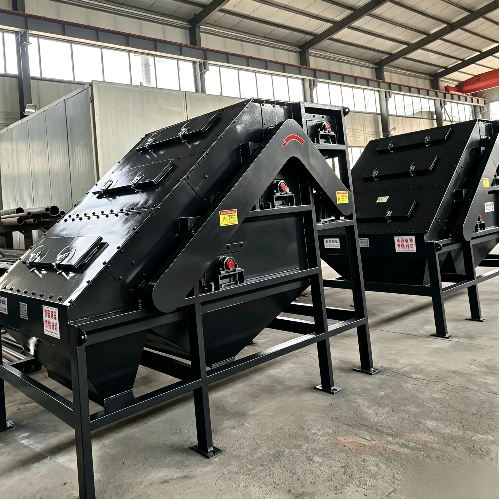
High Gradient Magnetic Separator
Construction of high gradient magnetic separator The separation principle of the high…

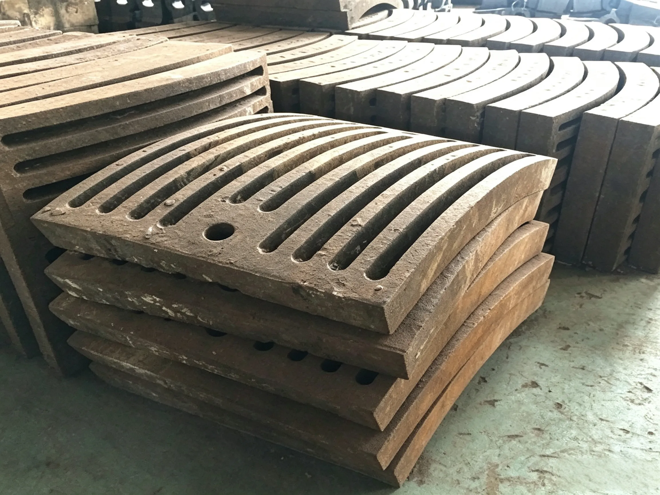
Broadly speaking, there are five types: concentric circular, radial, diagonal (oblique linear), polygonal, and herringbone (or chevron).
What should be the total slot area and the slot width of the partition diaphragm?
The slots of the partition diaphragm are designed for material passage. The slot width on the outlet face of the diaphragm is approximately 1.5 to 2.0 times that on the inlet face. The total slot area, also referred to as the effective area of the diaphragm, is expressed as a percentage of the diaphragm area. A larger effective area allows greater material throughput, but if it is too large, the strength of the diaphragm decreases. The effective area on the inlet face is typically 5% to 15%; for dry‑process closed‑circuit raw mills, it can reach 20%, while for wet‑process mills, a smaller value is preferable.
The slot width is related not only to the material throughput but also to the maximum particle size that can pass through, so it must be carefully controlled. In multi‑compartment tube mills used in the cement industry, the effective slot width (i.e., the inlet‑side width) of the first diaphragm is generally 6 to 14 mm, and for some raw mills it may be up to 16 mm. The effective slot width of the second diaphragm is usually 6 to 10 mm, and that of the third diaphragm is typically 5 to 8 mm. Based on practical experience in both domestic and overseas cement industries, the effective slot width of the first diaphragm should not be too large: for open‑circuit dry mills, 6 to 8 mm is recommended; for closed‑circuit dry mills, 8 to 12 mm; and for wet‑process raw mills, 3 to 7 mm.
The slot length is calculated according to the required open area and the effective slot width, and is generally 300 to 400 mm, with the longest abroad reaching 700 mm.
For the diaphragm of a two‑compartment coal mill, the effective slot width is generally 5 to 8 mm. The effective slot width of the discharge grate plate should be about 2 mm wider than that of the diaphragm, to facilitate material discharge and the removal of broken iron chips.
 English English
 Spanish
 Russian
 Arabic
 Swahili
 French
 Turkish
 Portuguese
 Korean
 Japanese
 German
 Italian